I wanted to add some exterior lights using the existing wiring, which would operate during the night. The most common way is to install a programmable timer switch before the lights, which is a hardware or software timer and a relay. However this needs to be installed indoors (unacceptable for my case) or outdoor, on a waterproof enclosure, which however can not be easily programmable.
The Hardware
So, instead, I used some simple components to create a switch using a relay. The switch is connected to the home WiFi, so it can be operated using any other client connected on the same network, or via the internet, if enabled. The circuit is housed in a IP55 junction box, near each light.
The main component of the circuit is the ESP8266 WiFi module, which includes a microcontroller and a TCP/IP stack. The ESP8266 needs a 3.3V supply, which is provided by the ac grid. Finally, a GPIO port operates a high voltage relay which connects the light. The following figure shows the complete circuit schematic.
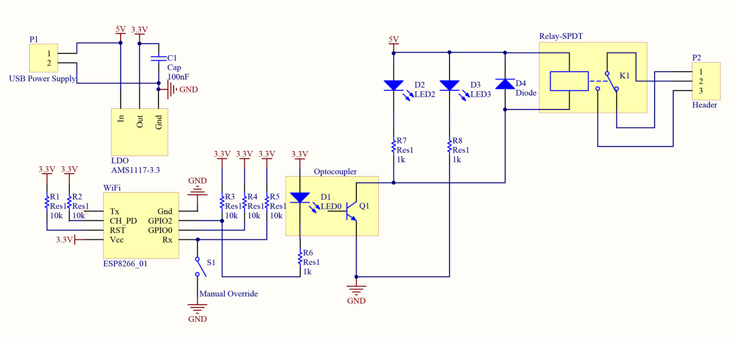
To provide the 3.3V, a USB power supply is used, together with a 3.3V LDO. The AMS1117 regulator needs to provide at least 9mA to operate correctly, so a resistive load needs to be added, together with bypass capacitors and a protection diode. For the current project, an external regulator board was used, which has all the necessary components. A supplemental 100nF capacitor is connected, since during transmission, the ESP8266 demands up to 250mA.
The ESP8266-01 module is used. The ESP8266 has many variants. Different boards, provide different ports. The ESP8266-01 board has the least amount of ports, two GPIOs and the UART peripheral Tx/Rx. For normal operation, during power-up, the GPIO2 needs to be high. The UART peripheral is not used during operation. So, Tx is not connected and Rx has a pull-up resistor, to not be affected by noise. The R3 resistor pulls GPIO2 to Vcc (although D1 does the same job by the manner it is connected). CH_PD enables the module, and needs to be pulled high. RST resets the module when low, so it is pulled to Vcc via R1. GPIO2 is used as an output to drive the relay, whereas GPIO0 is used an input to override manually the state, as it is (still) quicker than to connect via the mobile phone.
The light is connected via a high voltage relay (10A – 250V). Although for the current prototype an external relay board is used, it can be easily implemented in the same board, so it is analytically depicted in the circuit schematic. An optocoupler is used in the input, which can isolate the ground of the microcontroller with the ground of the relay. However, this is not necessary, as the relay provides isolation as well. LED3 shows that the relay is powered on, whereas LED2 shows if the relay is activated. The diode D4 is necessary, to dissipate the power of the relay coil. If this diode was not present, an overvoltage would occur during switch off, which could damage the nearby components. Connector P2 is a high current, high voltage connector.
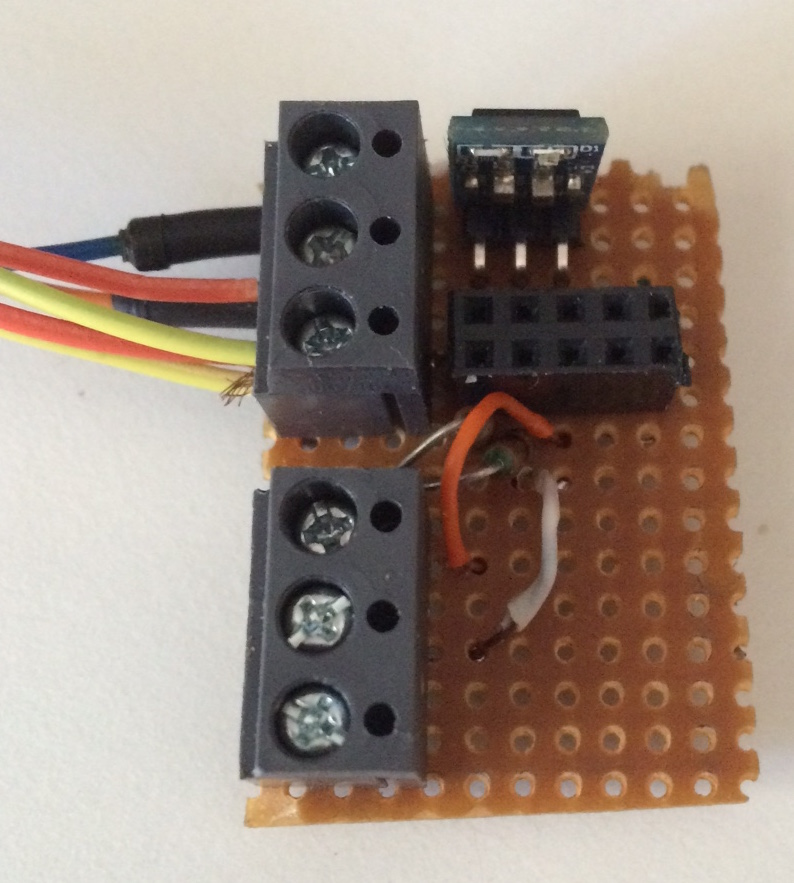
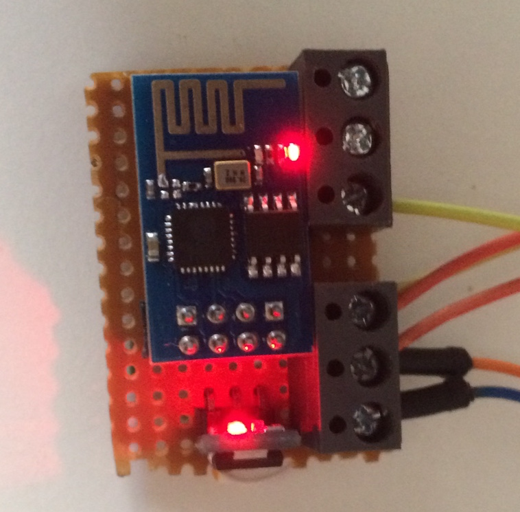
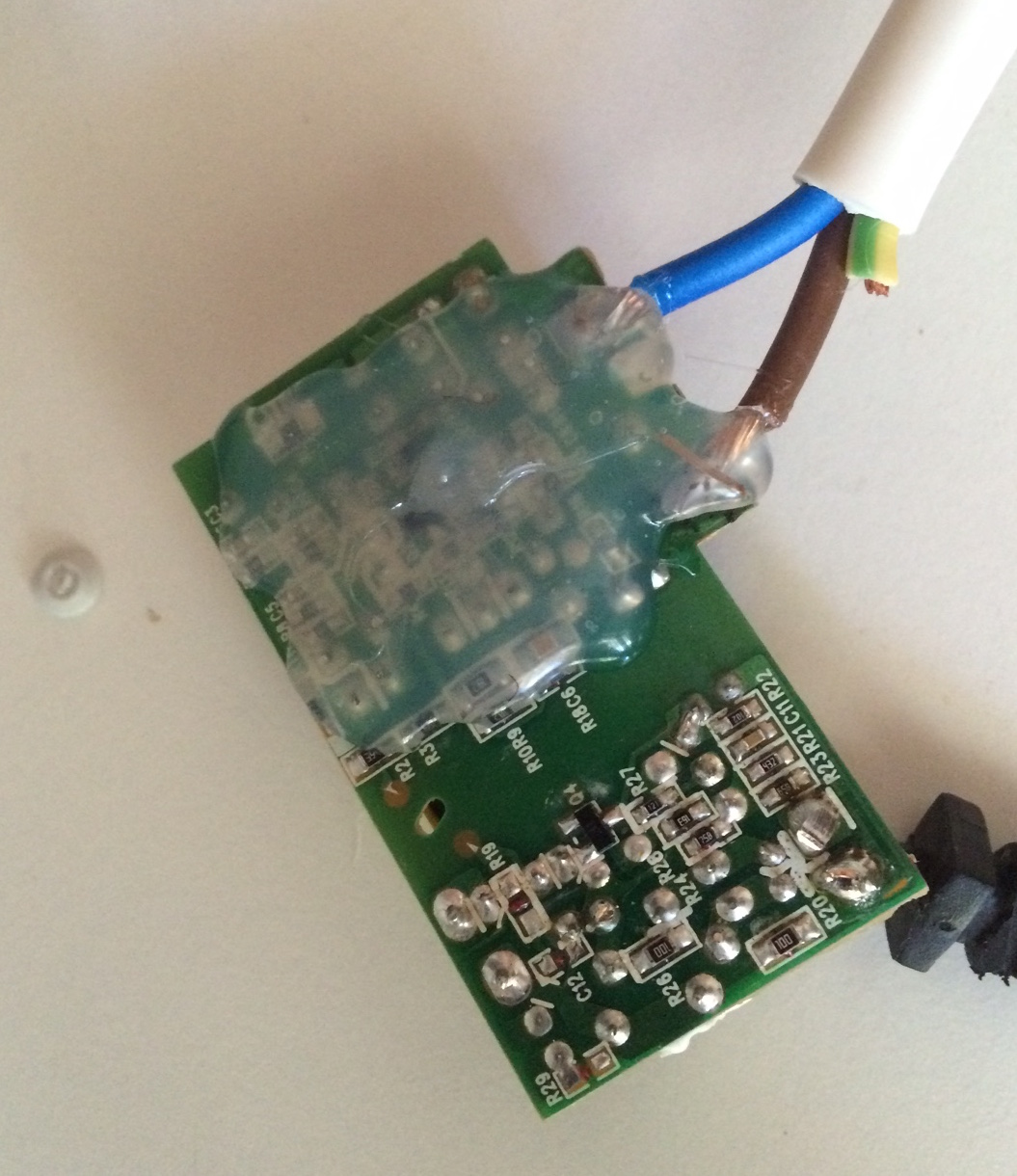
The ESP8266 module, together with the regulator board were installed on a single sided veroboard. A connector is used for the ESP8266 module, in order to remove it for programming.
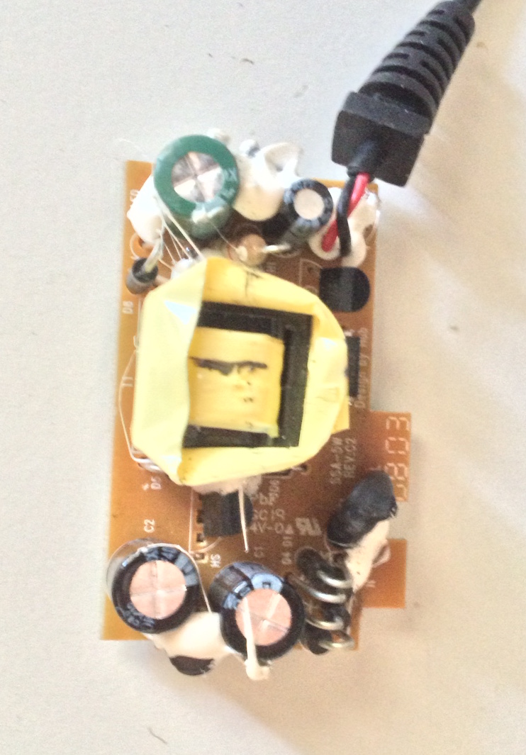
A 5V power supply from an old nokia bluetooth headset is used, which implements a flyback topology. The high voltage circuit (before the flyback transformer) is isolated with hot glue, to ensure that there will be no short circuiting when installed inside the enclosure.
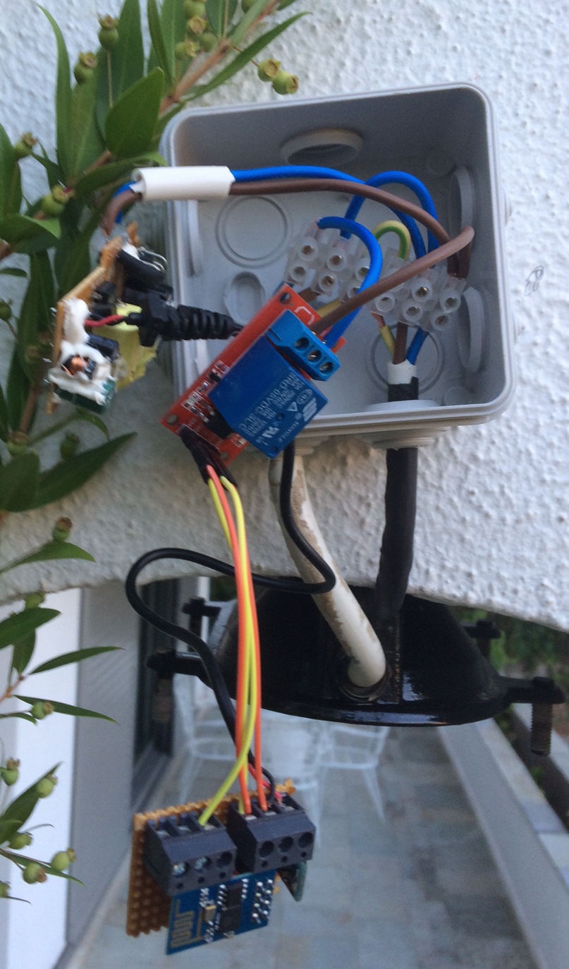
In this photo, the whole circuit is depicted. Power comes from the connector strip shown on the left. The neutral and ground are bridged to the light, whereas the phase passes through the relay. The 5V supply is powered by the phase and the neutral which powers the ESP8266 board through the LDO. The ESP8266 board provides power to the relay board, as well as the signal to switch on the relay.

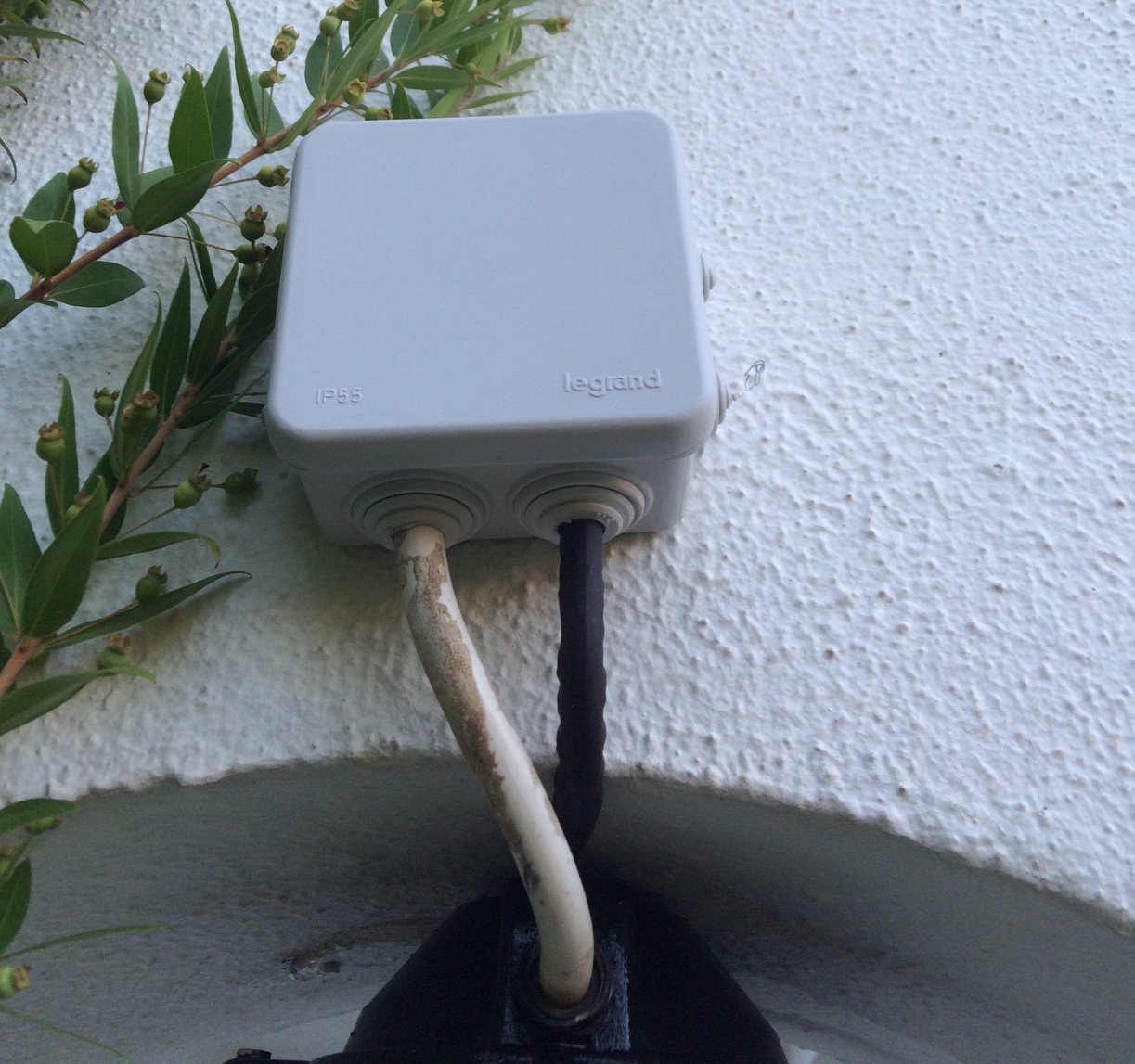
Finally, the installation is shown. A 8cm x 8cm waterproof (IP55) was used, although with careful wiring, the components could fit in a smaller enclosure. The optional manual override switch was not installed in this light box, as the installation hight makes it inaccessible to the user.
The Software
To recap, the ESP8266-01 wireless module has two GPIO pins (GPIO0 and GPIO2) and two UART pins (Tx and Rx).
- GPIO2 will be used as an output to control the relay, active low.
- GPIO0 will be used as an input to manually override the setting and activate the relay, active low.
- Tx will be be used for debugging, to read the microcontroller events
The ESP8266 is preloaded with some simple AT commands. There are many toolsets to program the module, but the easiest in my opinion is using the Arduino IDE, available on github. It supports all main functions and has a pretty good reference. Each time a new program is loaded on the microcontroller, the Arduino core is loaded as well, so it takes about a minute. To program the module, it needs to enter in bootloader mode, essentially to pull down GPIO0 before power up. To sum up:
Bootloader mode
- GPIO2: high
- GPIO0: low
- RST: high
- CH_PD: high
Normal mode
- GPIO2: high
- GPIO0: high
- RST: high
- CH_PD: high
The github page of the Arduino IDE for ESP8266 contains analytical instructions on how to install the toolset.
The developed program is a modification of the “WiFiWebServer” example with the following requirements:Connect automatically on the network
-
Create a webserver that every device (client) can access.
-
By accessing “http://<ESP8266IP>/gpio/0”, GPIO2 becomes low and the web server returns “ON”
-
By accessing “http://<ESP8266IP>/gpio/1”, GPIO2 becomes high and the web server returns “OFF”
-
By accessing “http://<ESP8266IP>/gpio/status”, the web server returns the status (“ON” or “OFF”)
-
-
If GPIO0 is low, the ESP8266 enters manual mode, meaning it sets GPIO2 low, discarding any change from the web
-
If the network connection is lost, the ESP8266 attempts to reconnect
-
If the ESP8266 gets an IP from a DHCP server *.*.0.*, it disconnects and tries to reconnect.
This last behavior programmed is due to the repeater found in the house. If the main router becomes inoperable, then the repeater acts as a DHCP server providing IP address 192.168.0.*. When the router is active again, then the ESP8266 does not change address and it becomes unreachable. So, if this occurs, then the module reconnects only when the main router is present again.
#include <ESP8266WiFi.h>
const char* ssid = "SSID";
const char* password = "PASSWORD";
int val=1;
int flag=0;
// Create an instance of the server
// specify the port to listen on as an argument
WiFiServer server(80);
void setup() {
WiFiBegin();
// Start the server
server.begin();
Serial.println("Server started");
}
void loop() {
if (WiFi.status() != WL_CONNECTED) {
Serial.println("WiFi lost, trying to reconnect");
setup();
}
if (digitalRead(0) == LOW && flag==0) {
val=0;
flag=1;
digitalWrite(2, val);
Serial.println("Manual");
delay(1);
return;
}
if (digitalRead(0) == HIGH && flag==1) {
flag=0;
val=1;
Serial.println("Auto");
delay(1);
return;
}
// Check if a client has connected
WiFiClient client = server.available();
if (!client) {
return;
}
// Wait until the client sends some data
Serial.println("new client");
while(!client.available()){
delay(1);
}
// Read the first line of the request
String req = client.readStringUntil('\r');
Serial.println(req);
client.flush();
// Match the request
if (req.indexOf("/gpio/0") != -1)
val = 1;
else if (req.indexOf("/gpio/1") != -1)
val = 0;
else if (req.indexOf("/gpio/status") != -1)
Serial.println("getting status");
else {
Serial.println("invalid request");
client.stop();
return;
}
// Set GPIO2 according to the request
digitalWrite(2, val);
client.flush();
// Prepare the response
String s = "HTTP/1.1 200 OK\r\nContent-Type: text/html\r\n\r\n<!DOCTYPE HTML>\r\n<html>\r\n";
s += (val)?"OFF":"ON";
s += "</html>\n";
// Send the response to the client
client.print(s);
delay(1);
Serial.println("Client disonnected");
// The client will actually be disconnected
// when the function returns and 'client' object is detroyed
}
void WiFiBegin(){
pinMode(2, OUTPUT);
digitalWrite(2, val);
pinMode(0, INPUT);
Serial.begin(115200);
delay(10);
// Connect to WiFi network
Serial.println();
Serial.println();
Serial.print("Connecting to ");
Serial.println(ssid);
WiFi.mode(WIFI_STA);
WiFi.begin(ssid, password);
while (WiFi.status() != WL_CONNECTED) {
delay(500);
Serial.print(".");
}
Serial.println("");
Serial.println("WiFi connected");
// Print the IP address
Serial.println(WiFi.localIP());
IPAddress IPadd = WiFi.localIP();
if (IPadd[2] == 0) {
Serial.println("Connected to repeater, disconnecting");
WiFi.disconnect();
}
}
The UNIX Client
The aim of the power switch is to control the exterior lighting, so it needs to switch on and off every day. A UNIX system using the cron scheduler seems the perfect implementation. As the system needs to be autonomous, in case the ESP8266 does not respond, the client needs to make several attempts before giving up. In the meantime, it needs to log every failed attempt (using logger) for future reference. The time between each attempt is doubled each time.
The DHCP server of the router is configured to give a permanent IP address to the ESP8266 module. The above requirements are embedded in a bash script. The script is used with two arguments, the first is the ip and the second is the state (0, 1 or status).
#!/bin/bash
arguments=$#
max_attempts=10 #maximum attempts to try to connect
timeout=2 #initial timeout in seconds
attempt=0
if [ "$arguments" -ne "2" ]
then echo "usage: setstate <ip> <state>"
exit 1
fi
dev=$1
state=$2
url="http://"$dev"/gpio/"$state
while (($attempt &lt; $max_attempts)) do curl -s --max-time 1 $url > /dev/null
exitCode=$?
if [[ $exitCode == 0 ]]
then
break
fi
logger -p error "[WARNING] Wireless $ip not responding, retrying in $timeout"
echo "Failure! Retrying in $timeout.." 1>&2
sleep $timeout
attempt=$(( attempt + 1 ))
timeout=$(( timeout * 2 ))
done
if [[ $exitCode != 0 ]]
then
logger -p error "[ERROR] Wireless $ip not responding"
echo "Maximum attempts reached trying to connect ($@)" 1>&2
fi
exit $exitCode
The full project for the ESP8266 power switch can be found on my Github page.