The autonomous PPC power plant in Kos supplies electrical power to island, as well as the surrounding islands of Kalymnos, Nisyros, Tilos, Leros and Lipsi, with underwater cables. The construction started in 1994, to replace the power plant which existed in Marmari. The current nominal power is 90MVA, however the power of four wind farms are connected to the plant, 2 in Kos and 2 in Leros, as well as a smaller 10MVA plant in Kalymnos. The plant belongs to "Island Production Administration" of PPC and is currently the third largest island plant, after the one in Crete and the one in Rhodos.
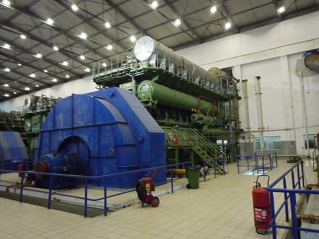
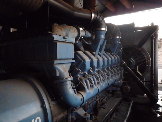
The main engines are powered with crude oil and the smaller ones with Diesel. In the main engine room there are 6 main generators and have a consumption of 200g/kWhr.
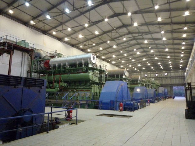
The first engine is a four stroke, supplied by Fincantiery. The paired generator is built by Ansaldo and has a nominal power of 8MVA.
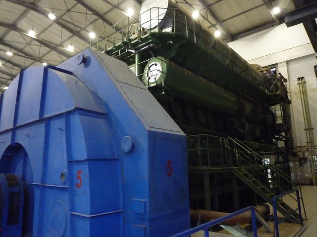
The following 3 engines are two stroke, supplied by MAN. Their generators have a nominal power of 11.6MVA.
Finally, the two larger ones, are also two stroke and byilt by MAN. Their nominal power is 16MVA.
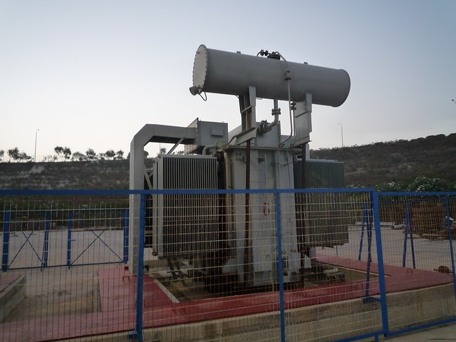
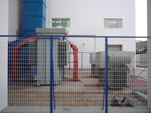
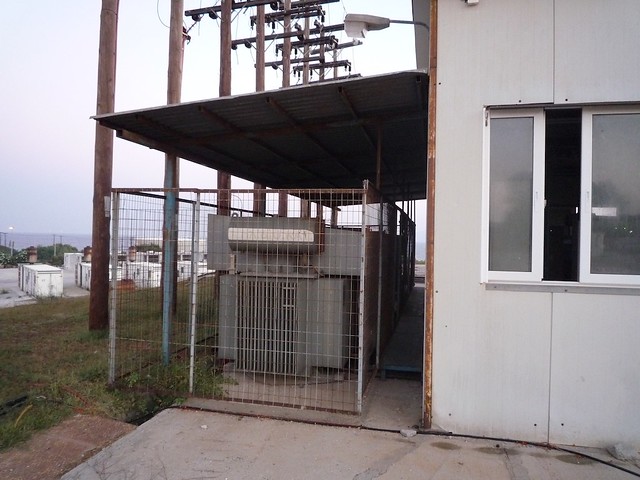
The generator nominal voltage is 6,3kV and is stepped up to 20kV by the transformers of equivalent power, located outside the engine room. The first picture shows the transformer the 16MVA generator, whereas the second shows the one for the 11,6MVA generator as well step-down transforemrs to 400V for local service. The total consumption of the plant is approximately 2MW.
The crude oil is provided by a tanker every 2-4 weeks, depending on the season and is stored in large tanks. It is then purified by special machines (delaval) and stored in smaller tanks. In order to be used by the machines, the oil must be preheated. This is done harnessing the heat of the exhaust gases, which have a temperature of over 300C.
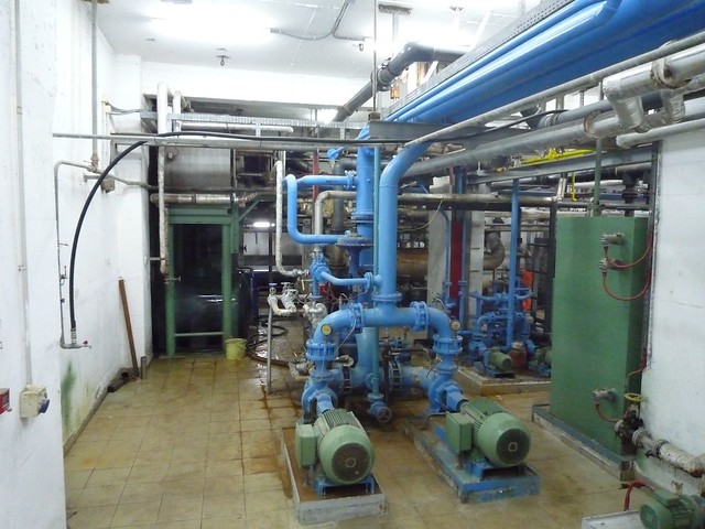
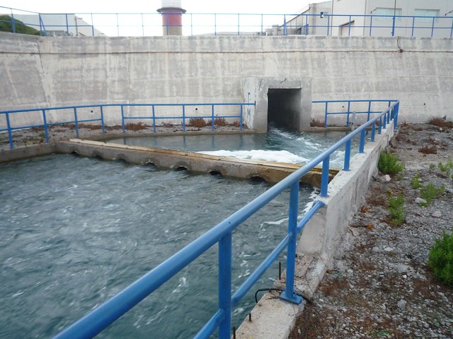
Engine cooling is done using sea water. There is a sea level well which drives naturally the water near the engine room. It is then filtered and pumped to the engine room.
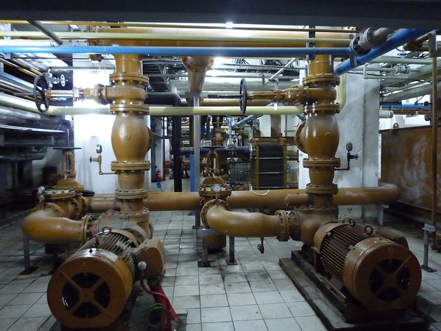
Below the machines, there is a wide network of pipes transoporint oil, fuel and water. To reduce the chance of mixing engine oil with sea water, the different circuits are well far from one another. The oil is inserted in a cooler which drops the temperature using water. This water is inserted into a second cooler, which is cooled by the sea water. This water is changed regularly, to avoid contamination of the sea water.
Finally, sea water is driven from the engine room back to the sea. In case of a leak, the oil, as it is lighter than the water, will float to the surface, which is why, there are two barriers before the water returns to the sea. In those barriers there are pipes on the bottom, so that the water at the lowest point passes to the next level.
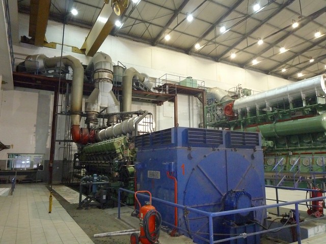
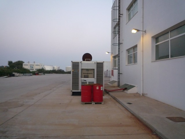
Outside of the engine room, there are other diesel generators. The first one has a nominal power of 1MVA and is used in case of a black out, in order to power all the subsystems for engine start. During periods of high demand, it can be used as well during peaks.
The rest of the generators are located away from the main engine room.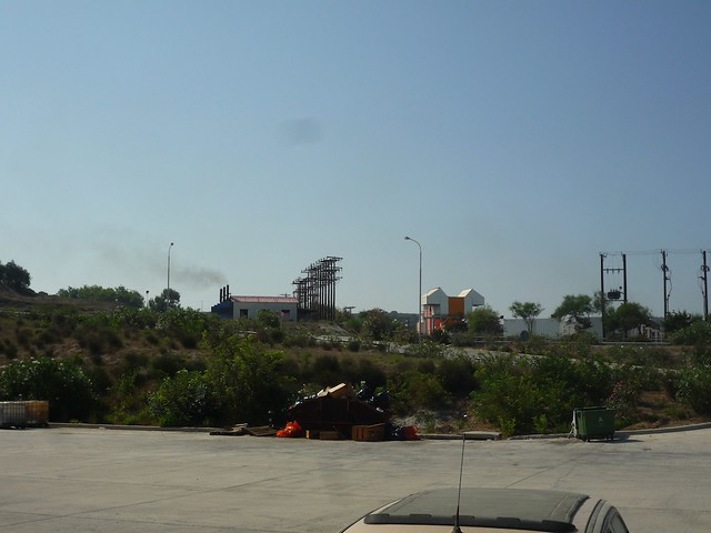
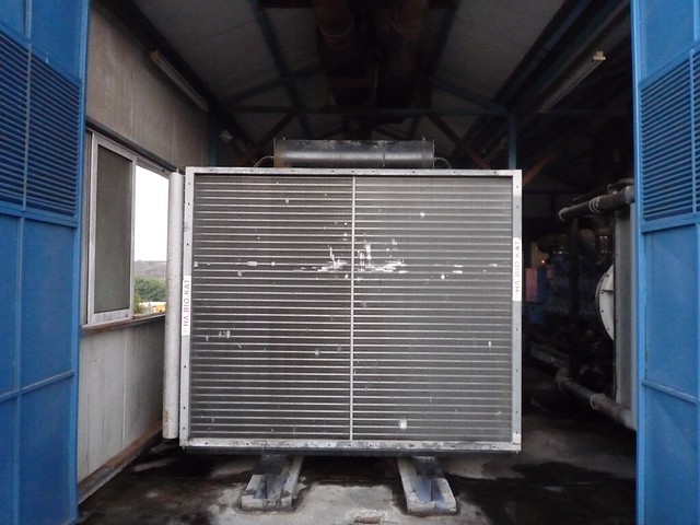
On the left of the pictures, the MTUs can be seen. There are 3 motor-generator pairs, of nominal power 1,25MVA each, but with poor efficiency and high noise level. That is why they are the last generators which will be connected, depending on the energy demand. In the following pictures, the motor, the transformer and the cooler can be seen. Because during the plant construction, in this area, auxiliary machines where connected in order to supply the energy for the constructions, 17 poles remain in place, to which the MTUs are connected.
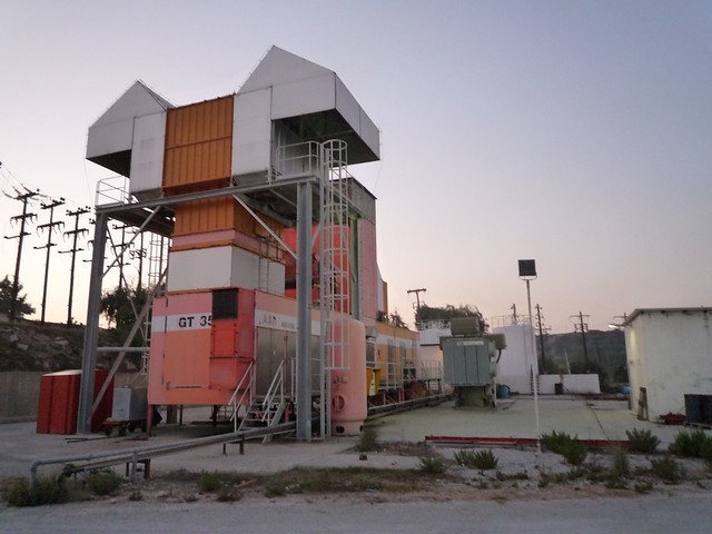
Close to the MTUs, there is the gas turbine generator, of 14MVA nominal power, constructed by ABB. It uses the kinetic energy of the exhaust gas which are produced by the combustion of diesel, in order to rotate a turbine. In the following picture, the main construction can be seen, together with the equivalent transformer. All the switches are pneumatically controlled, like the ones in the other motors as well. The tank shown, contains pressurized air, for engine operation, as well as for fire up. The air pressure is generated by two compressors.
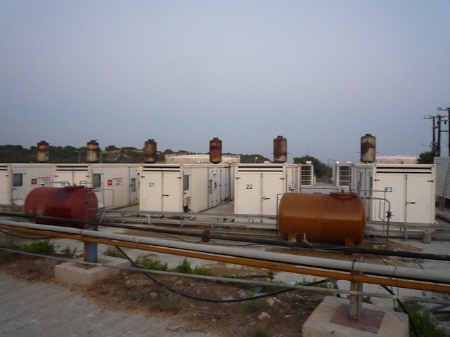
The last generators are the group of 12 portables. They are the newest ones in the station, made in Italy, with a nominal power of 1,25MVA each. They use diesel fuel and the transformer is found inside the container. There are also two auxiliary containers, one for circuit breakers and one for control.
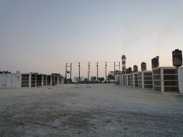
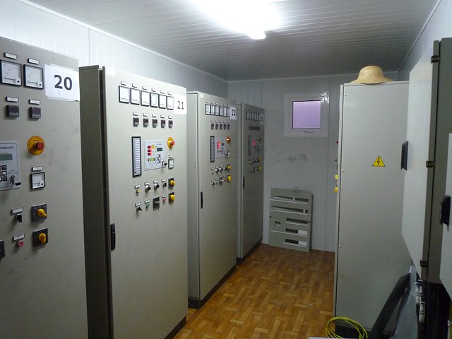
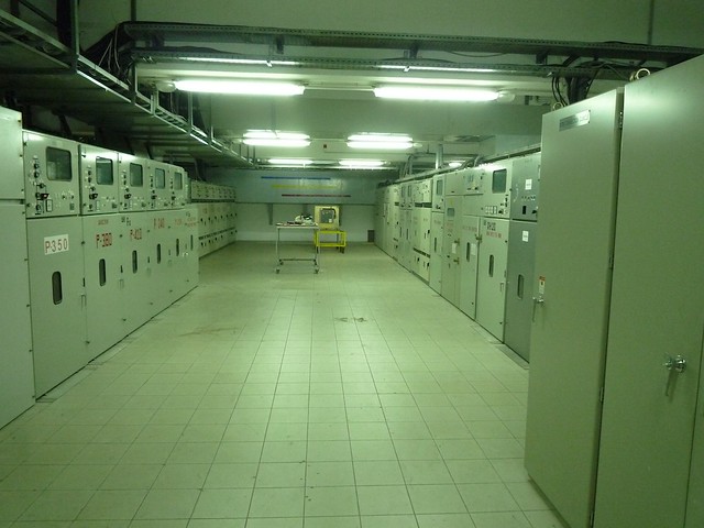
The power of all the generators is supplied to the grid, to be distribuded via the transmission lines. The following picture shows the room where all the transmission line breakers are located.