Power Electronics for motor control have evolved over the decades: DC machines were replaced by AC induction motors and nowadays permanent magnet synchronous machines (PMSM) are also very popular, in particular in the automotive industry. Field oriented control has also enabled this transition, as it enables AC driven machines to be controlled with constant (direct) values and references.
TI provides the 2MTR-Dyno, a configuration where two 100W permanent magnet synchronous machines are coupled together. They are driven by three-phase inverters (also available by TI), which share a common DC link. As such, the energy floats between the two inverters (since when one machine is motoring, the second one is in regeneration and vice versa) and an external DC power supply is there to keep a steady DC link voltage and provide power to compensate for the losses for the drive system.
TI also provides a library and example projects to drive both motors with Field Oriented Control and Space Vector Modulation. I decided to write my own algorithm for FOC on a Xilinx Zynq SOC. My Zynq board would drive the inverter of one motor, whereas a TI TMS320F28379D launchpad would drive the second motor. The steps to use the TI setup to control a motor are detailed on a previous post.
The Hardware
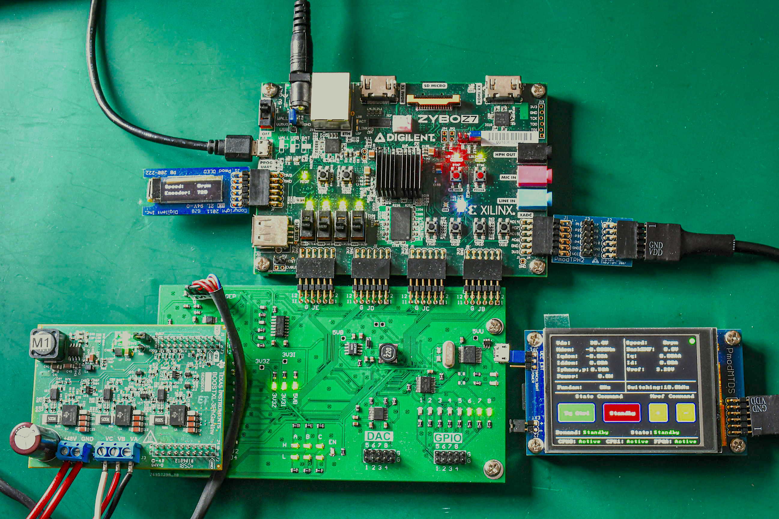
The hardware setup comprises of three components: motor, inverter and embedded controller.
Motor
The motor is a permanent magnet synchronous three-phase phase motor with 4 pole pairs, capable of 7000rpm and 0.27Nm. Apart from the three-phase power outputs it also has a 4000count quadrature encoder, powered by 5V.
Inverter
I have used a BOOST-XL GaN inverter from TI, compatible with the 2MTR-Dyno configuration. The board includes a three-phase inverter using GaN transistors with a nominal DC link voltage of 48V. The board also has 3x phase current sensors a DC link voltage senosr, which output the measurements in 0V to 3.3V values on the inverter terminals. It also has an overcurrent protection circuit as well as an overtemperature protection circuit, together with a auxilary power supply, which generates the low power voltage rails from the DC link.
Embedded Controller
For this project, I have used a Digilent Zybo Z7 board, based on the Xilinx Zynq-7020 SOC. The Zynq SOC has two ARM-Cortex A9 processors and 7-series FPGA logic. The board also has useful (for this project) peripherals, such as a 1GB DDR memory, UART to USB interface, multiple buttons, switches and LEDs (mapped either to the processor area or to the FPGA area) and multiple IOs (PMODs) to connect other boards. I have used two PMOD connectors to add two external displays from Digilent, an OLED one that shows the motor encoder information and a touch one, which shows the inverter state, key measurement values and also has buttons to control the inverter and the demanded torque.
Between the inverter and the Zynq board, an intermediate board was added, to house the glue logic between the two different boards: the voltage translation for the encoder signals, the analog to digital conversion for multiple inverter signals (currents and voltages), the buffers and pull resistors for the PWM signals, a digital to analog converter and header, a uart to usb interface as well as a digital header for debugging purposes and many LEDs. Each function of this daughter board is detailed below.
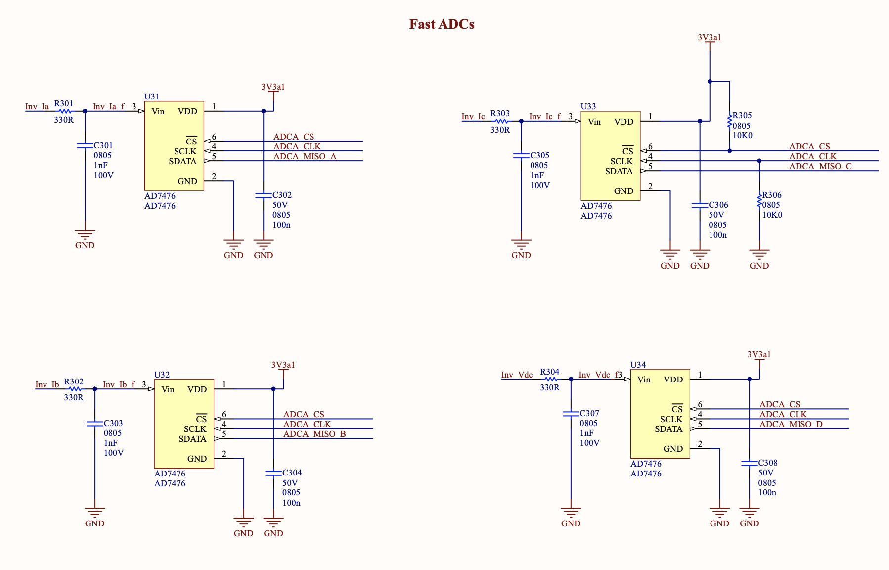
For the field oriented control, the most critical and time sensitive inputs are the rotor position and the three phase currents. The DC link voltage is also important (for the feeforward controller as well as for overvoltage/undervoltage protection), but doesn't need to be sampled on every switching period, whereas the previous inputs do. Moreover, as during normal operation, there is no leakage current expected in the motor, the sum of the three phase currents is zero, so only two phase current measurements are needed. However, this daughterboard has ADCs for all three phase currents, as well as for the DC link voltage measurement. The analog signals are fed to 4x independent Analog Devices A7476 SPI ADCs, which are then connected to the FPGA fabric. The ADCs share the same Chip Select (CS) and Clock pins. With this approach, the converted values are transferred to the FPGA in parallel between the four channels, taking advantage of the parallel capabilities of the FPGA. Moreover, with this approach, we ensure that all four signals are sampled at the same time (as soon as the CS pin goes low).
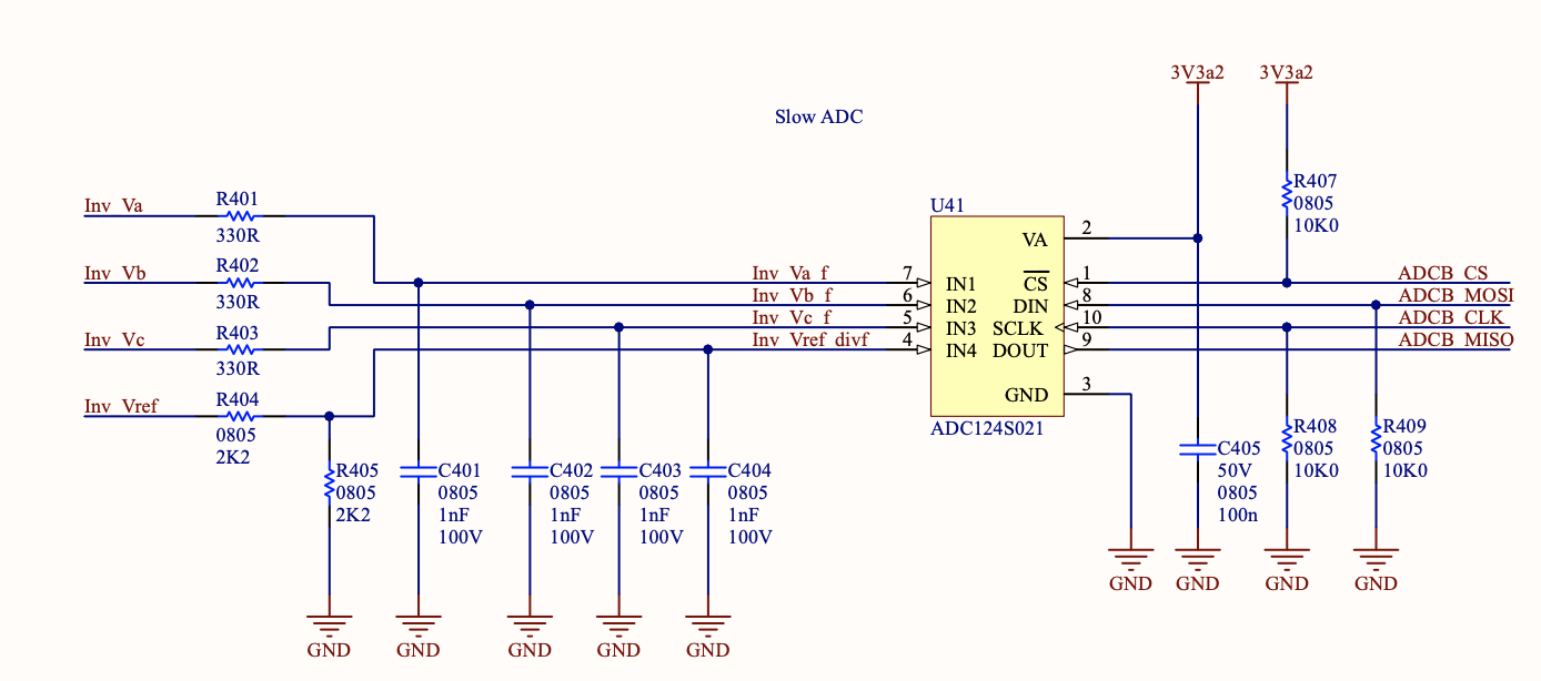 The inverter also outputs the phase voltage, which are not needed for the Field Oriented Control algorithm, but could be used for secondary protections, or debugging. Those voltages are fed to a TI ADC124S021 SPI ADC, together an image of the Inverter board Vref input, to be compared to the Zybo 3V3 rail. The conversions of those four channels are done sequentially. The SPI channel is also connected to the FPGA fabric.
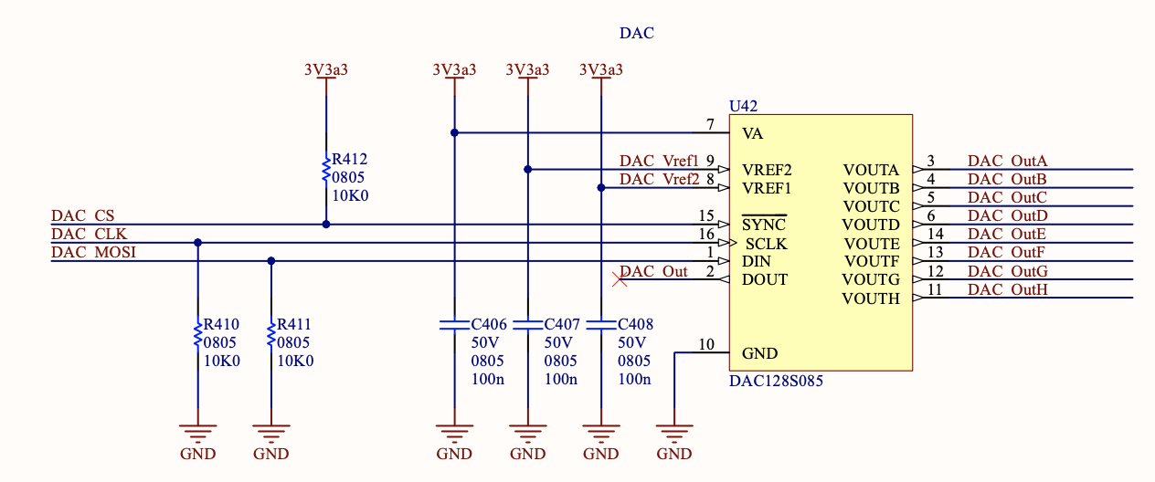 A Digital to Analog Converter (DAC) is also added on the daughterboard. The DAC is the TI DAC128S, controlled over SPI from the FPGA fabric. It is used to output various internal control signals (e.g. rotor angle, measured currents, calculated current values on the rotating frame, duty cycle values etc.)
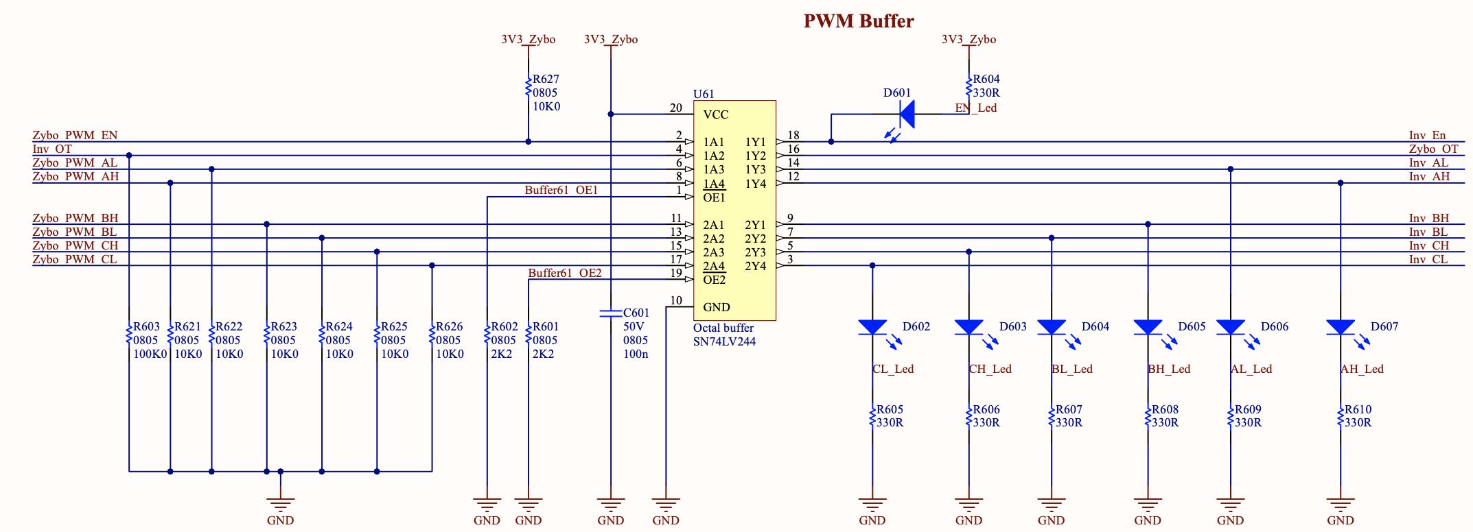
The output of the controller is 6x pulses for the three-phase inverter bridge. Those pulses are also generated by the FPGA fabric. As those signals are outputs of the Zybo board, to protect the SOC, a buffer is used as glue logic between the two boards. The inverter overtemperature pin goes through the buffer as well. LEDs are placed on the buffer output to show the state of each digital signal. The necessary pull resistors are placed on the buffer inputs, to ensure that the inverter does not switch-on when the SOC is in reset or initialization state.
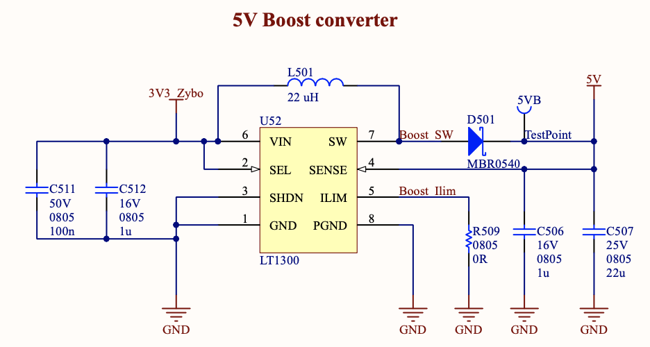
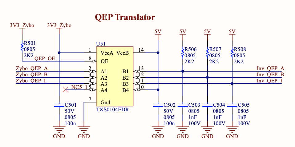
The motor quadrature encoder interface needs to be powered by 5V. Therefore, a 3.3V to 5V Boost converter is added to the board, using the Linear Technology LT1300 IC. The three quadrature encoder signals (A, B and index) are passed through a TI TXS0104 voltage translator, which acts as a buffer between the motor connector and the zybo connector. Those signals are sent to the FPGA fabric, where the logic to determine the rotor angle is.
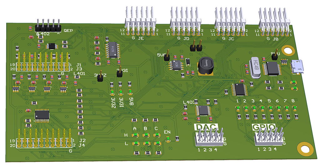
A two-layer board was built to house all of the above functions. The board dimensions were constrained by the connector locations. The LEDs were placed on easy to see places and the debugging connectors (DAC, GPIO, USB) were placed away from the connecting boards. All the components were placed on the top side, which eased assembly and probing.
The Software
The software functions can be split into two categories; functions that were implemented on the FPGA and functions that were implemented on one of the two ARM cores.
FPGA fabric
The FPGA is used to interface with the different board peripherals. More specifically:
- Analog Measurements: The FPGA gets a trigger signal during every PWM cycle. It starts a transaction through SPI to sample and convert all the time-critical analog measurements (3x phase current measurements + DC link voltage measurement) together with the less important measurements from the auxiliary ADC
- Encoder value: The quadrature encoder sends two phase shifted pulse sequences while the rotor is spinning. The FPGA constantly monitors the encoder signal to determine the rotor angle and speed. Whenever it is commanded by the microcontroller, the logic sends those two measurements
- PWM output: The PWM module gets the duty cycle for each half-bridge switches as well as the inverter switching frequency setting. It then applies a dead time between the signal and outputs the 6 different pulses, it also outputs an interrupt signal twice per PWM cycle (at the center and at the end of the cycle). As Space Vector Modulation is used, during the interrupt either all the high side or low side switches are on, so it is the best position to do the sampling of the analog values.
ARM Core
There are two ARM cores on the Zynq SOC, Core 0 and Core 1, both of them are used for the Field Oriented Control.
Core 0 is performing the high level motor control algorithm. It is responsible to enable Core 1, display key values to the two screens, scan the touch screen for any input and calculate the reference Quadrature and Direct current values, based on the demanded torque (set on the touchscreen) and speed (the controller supports field weakening control for high speed operation).
Core 1 does the low level motor control algorithm, the loop of which is done once or twice every switching period. At the beginning of the loop, the analog signals are sampled (phase currents and dc link voltage), by sending a request to the FPGA fabric. Another request is sent to the fabric to get the rotor encoder position and speed. Based on these values, the Clarke and Park transformation is applied, in order to get the quadrature and direct measured values. Those values are compared to the reference demanded values and the errors are fed into a PI controller, which outputs a quadrature and direct voltage demand. Those two values are added to feedforward voltage demands, the values of which are calculated based on the motor equations. Based on those values, as well as on the expected rotor position for the next duty cycle, the voltage phasor is calculated. The amplitude and phase of the phasor determines each half-bridge duty cycle, which is calculated through the Space Vector Modulation algorithm. During the loop, the analog measurements are also checked to ensure that the inverter does not exceed its safe operating area (current, voltage and motor speed) and can send a signal to the FPGA fabric to stop any operation, in case it does.
Data Buffer
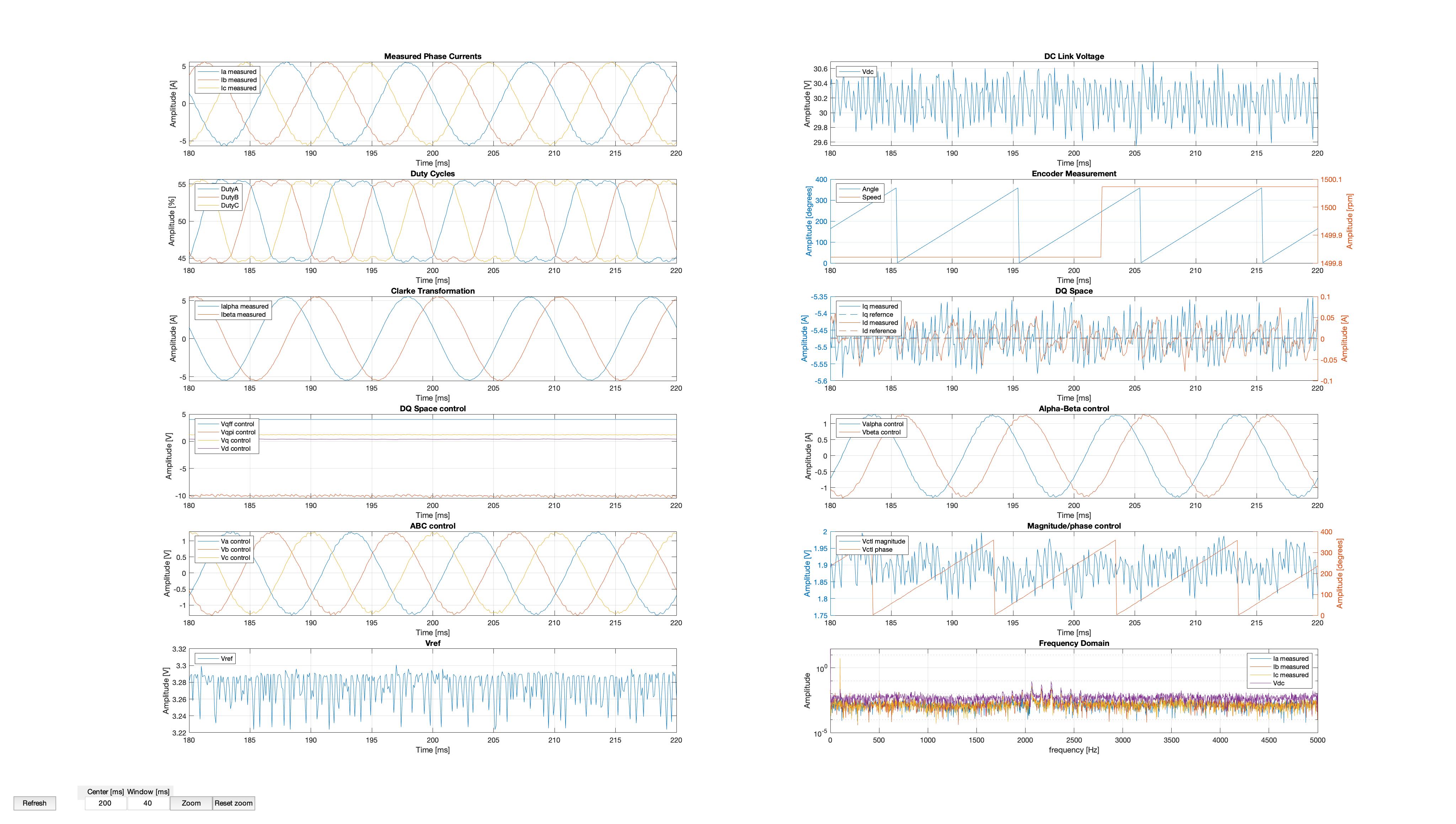
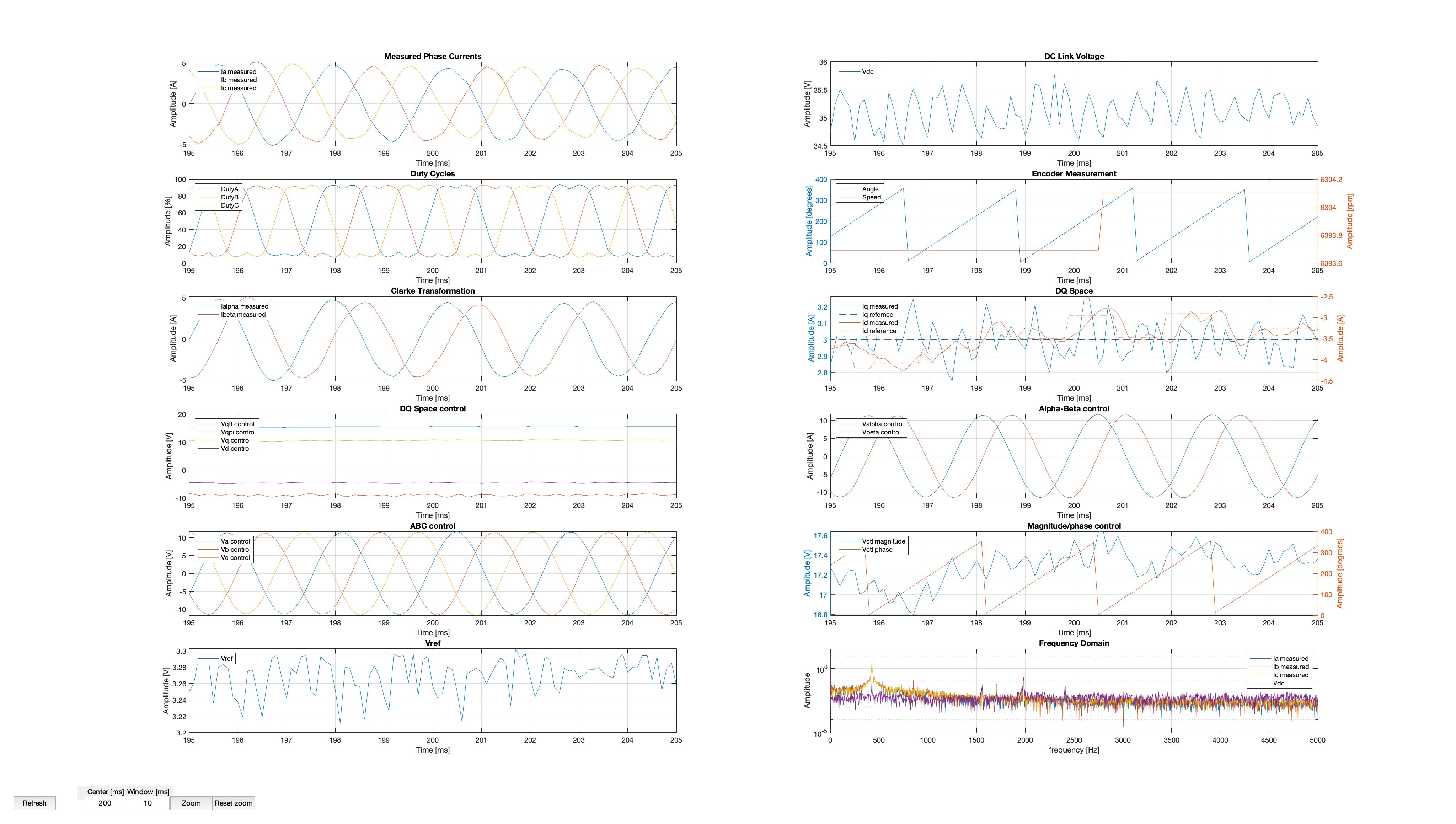
As analyzed above, once or twice per PWM cycle, all the analog signals must be sampled and multiple calculations need to be made. The Zybo board has a 1GB DDR memory, which can store a vast amount of information. All the calculations for each low level control loop are stored in a circular buffer on the memory. The buffer can be stopped manually or during a fault and can then be read offline, to get the operating condition just before the fault. The data buffer is downloaded and a Matlab script is used to plot all the details, as will be shown below.
Test Results
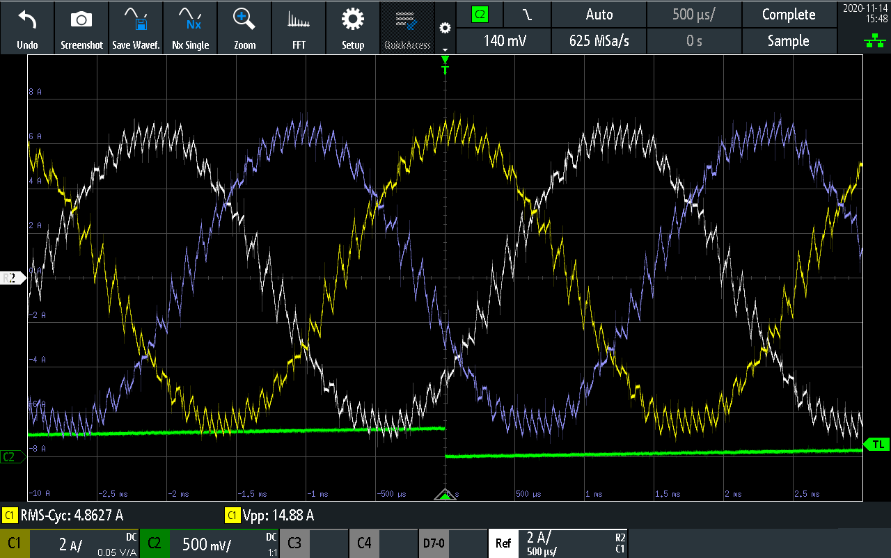
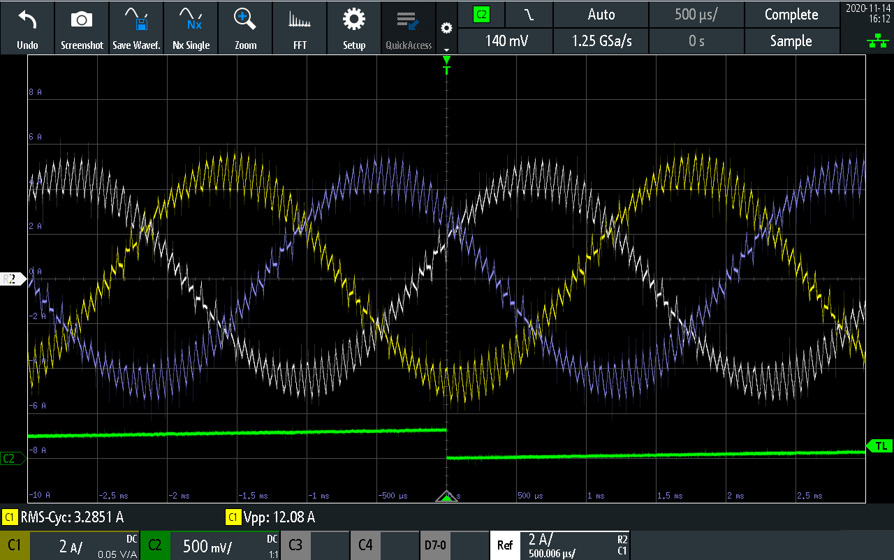
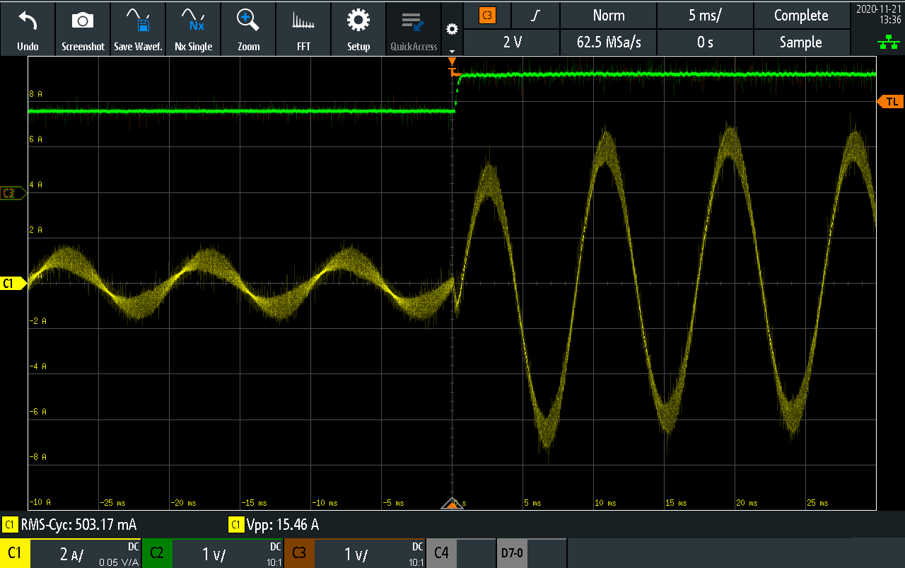
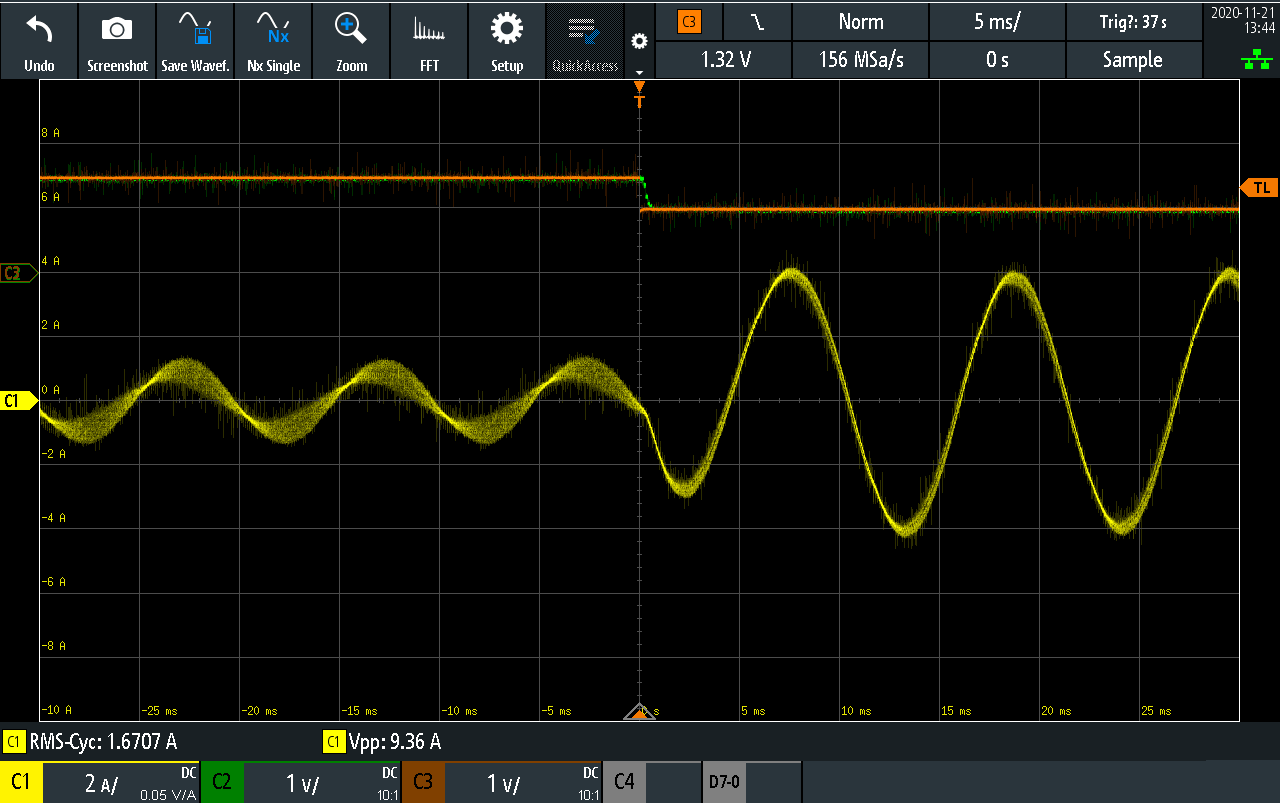
To verify the developed motor control algorithm, multiple tests have been done on the drive system. The load motor was controlled by the TI microcontroller board, running the TI control algorithm, operating in speed control. The developed board was controlling the torque of the master motor. The phase currents are measured with an oscilloscope, whereas the key values of each PWM cycle during various operating point are plotted through Matlab.
Operation at low speed (1500rpm) and positive torque (+0.25Nm)
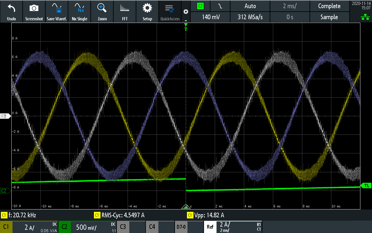
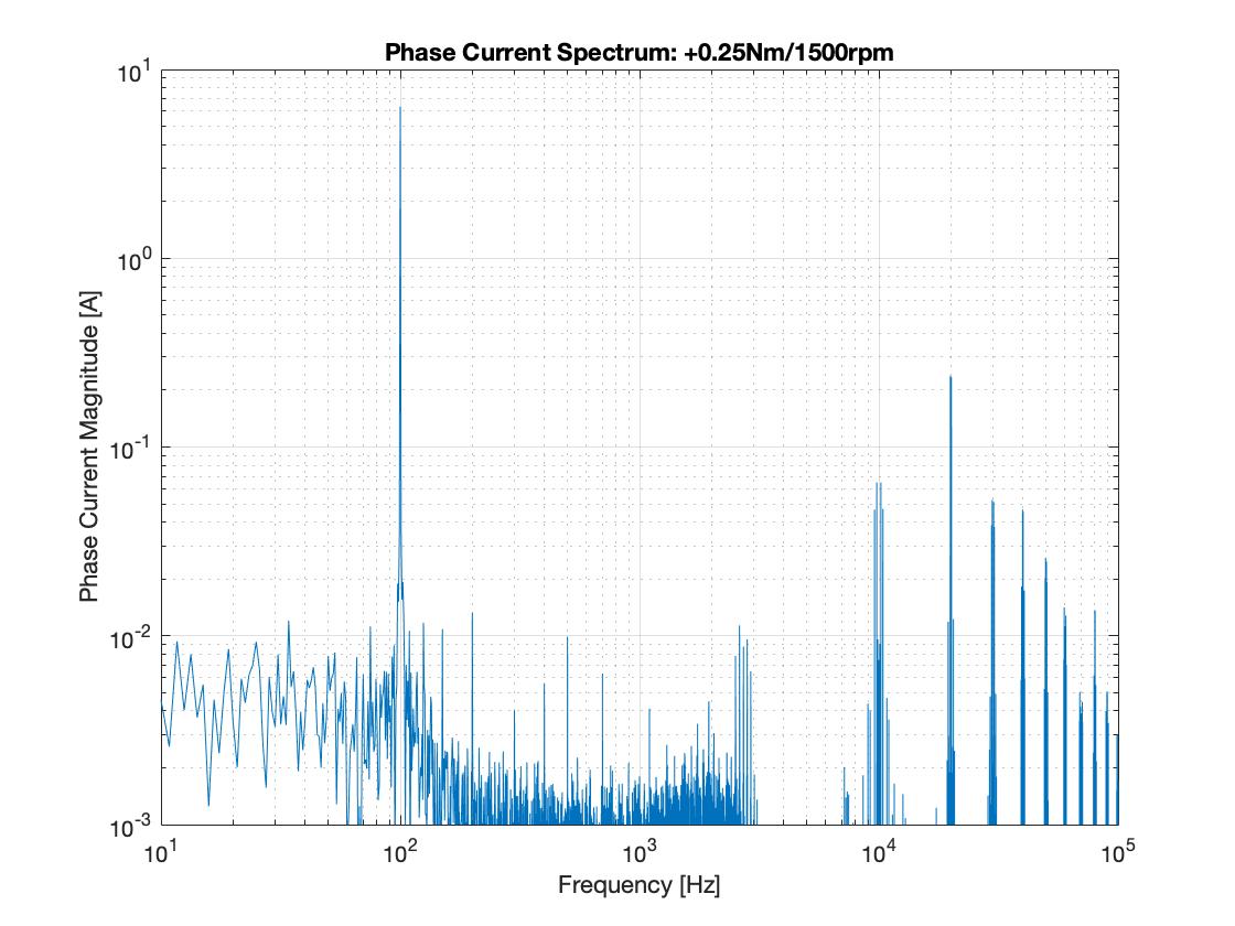
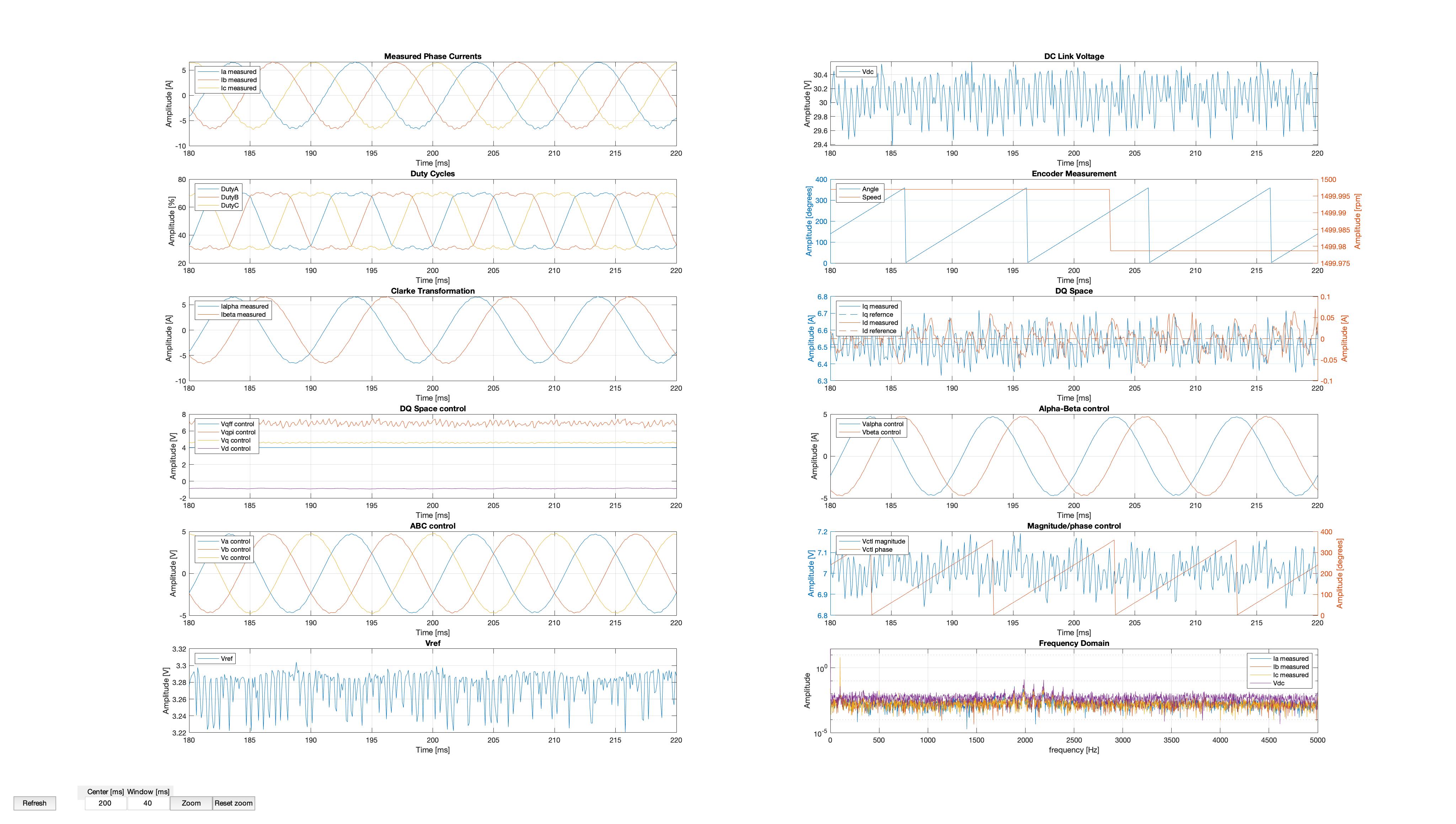
As can be seen, the three phase currents on the motor have 120degree offset between them and are very sinusoidal. The demanded Quadrature current is 6.5A and Direct current is 0A, resulting to a peak phase current of 6.5A. Indeed, the oscilloscope traces show that the current of each phase reaches this value.
Operation at low speed (1500rpm) and negative torque (-0.21Nm)
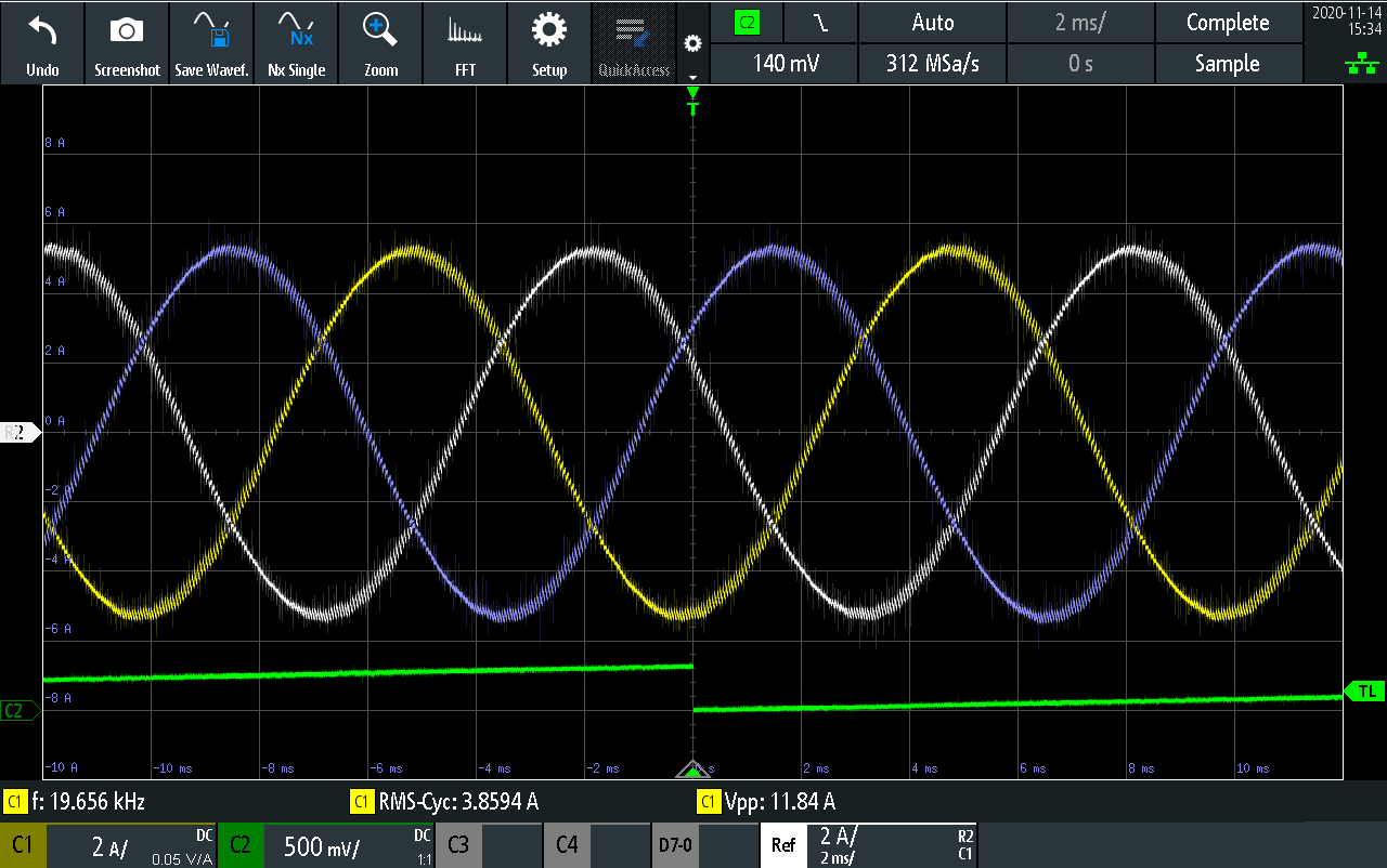
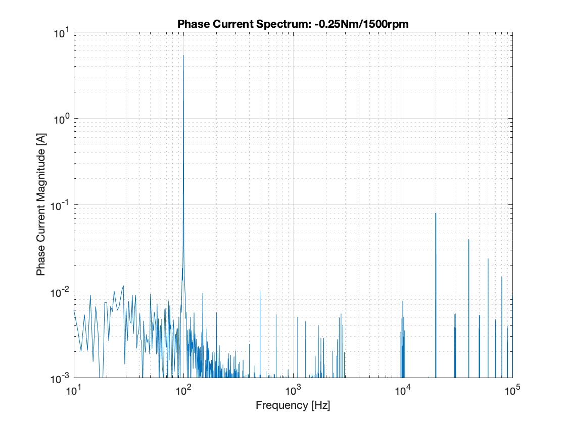
Similar is the behaviour for negative torque. The direct current reference is still zero, but the quadrature reference is now negative. This leads to a smaller phasor magnitude and smaller duty cycle. The demanded torque amplitude is smaller than the one of the positive torque example, due to the limitation of the TI side maximum torque. Still, the current waveforms are very sinusoidal and the control does not show any oscillation.
Operation at medium speed (4500rpm) and positive torque (+0.25Nm)
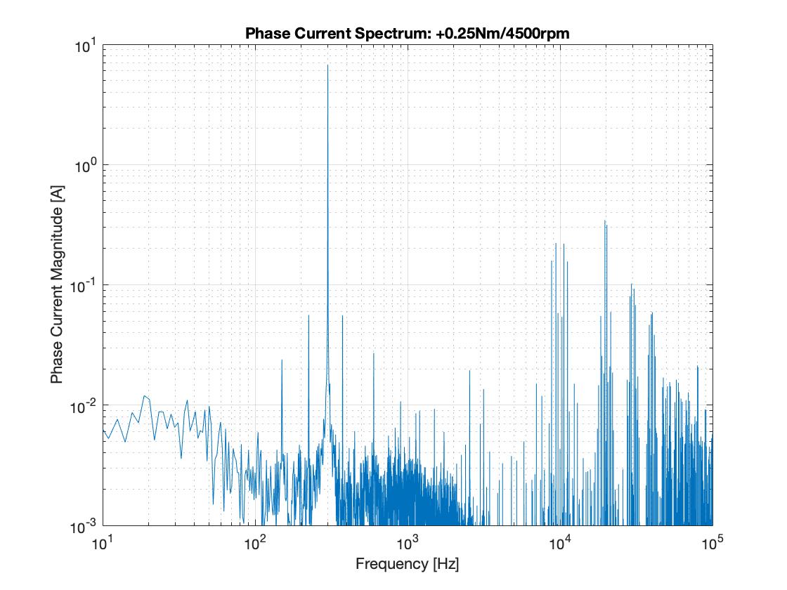
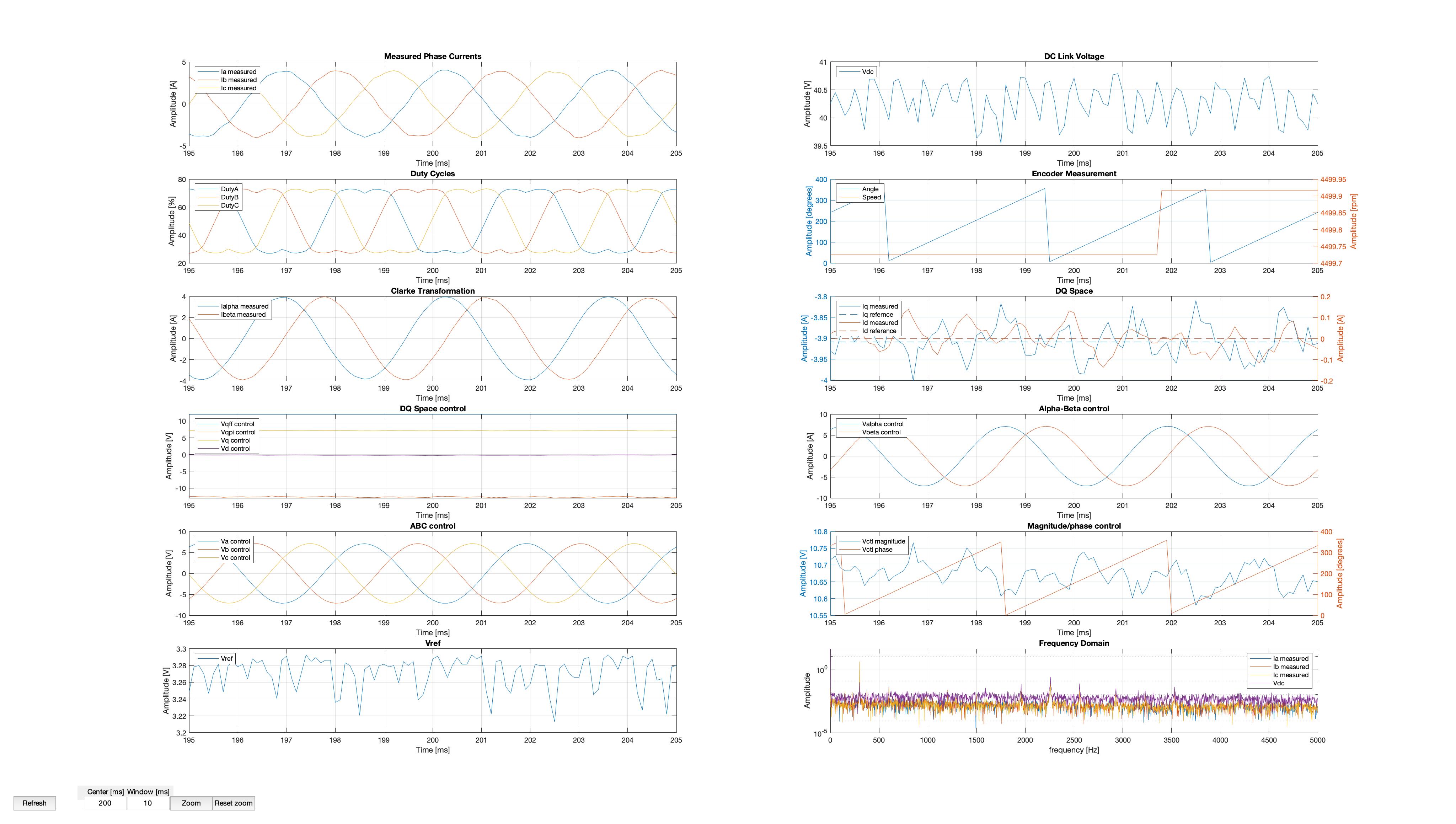
As the switching frequency on this example is constant (10kHz), a higher rotating speed means higher motor fundamental frequency, which results to a higher ripple on the current. However, the current still remains sinusoidal and the controller isn't affected by the lower number of sampling points per fundamental period. The TI controller does not support field weakening operation, so no tests were done with high speed and high torque.
Operation at medium speed (4500rpm) and negative torque (-0.15Nm)
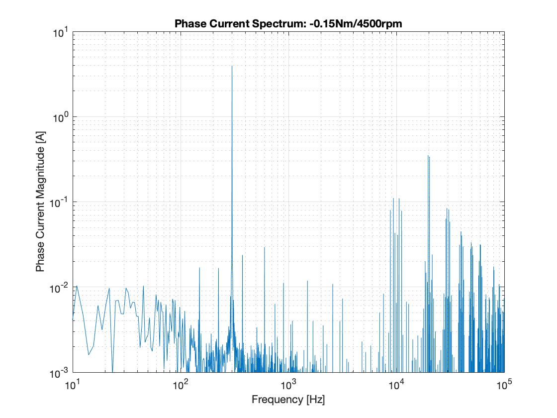
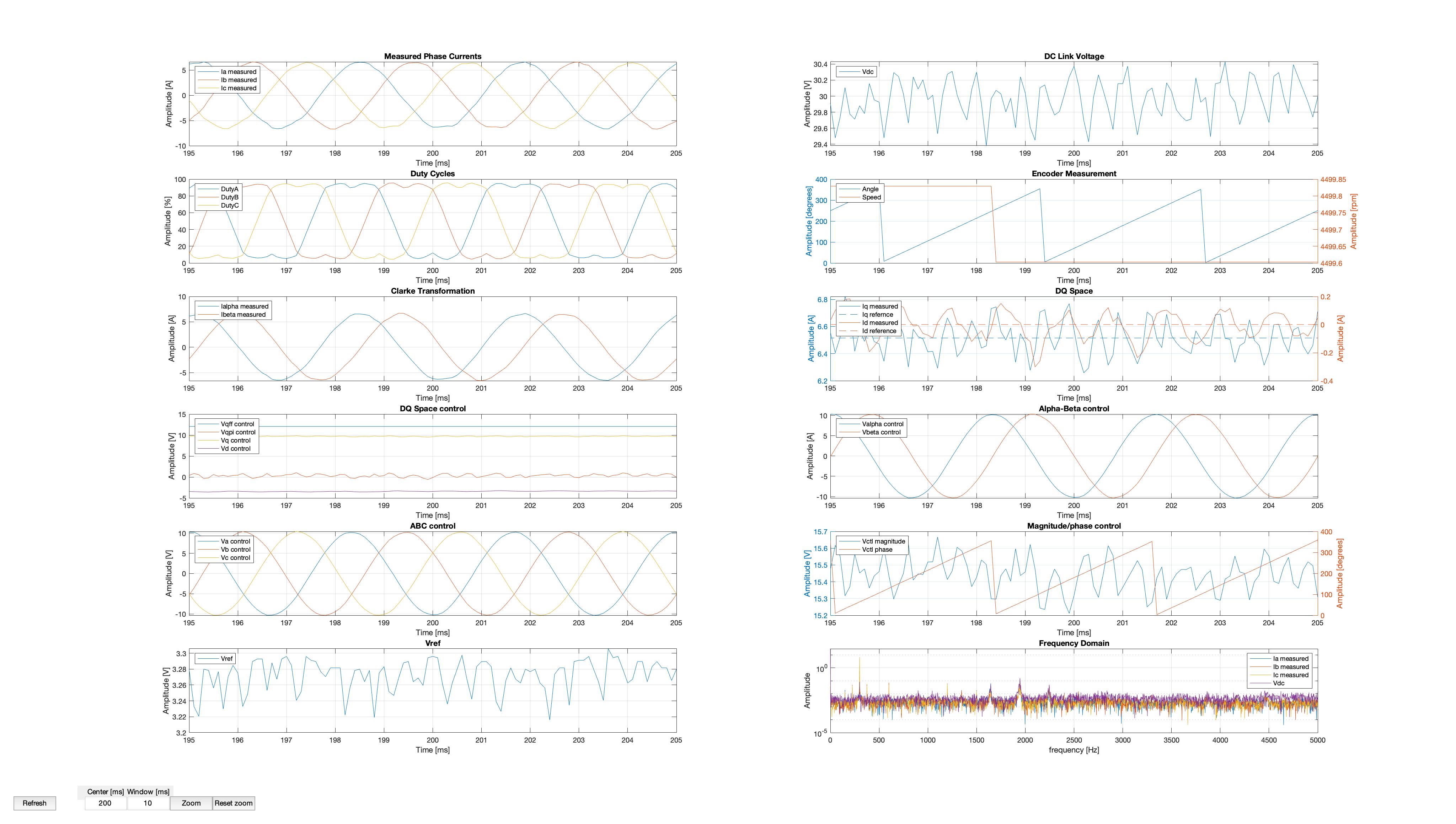
Operation and medium and negative torque was also limited by the TI controller, so tests were done at a lower torque amplitude. Again, the developed algorithm wasn't affected by the increased speed or negative torque, and showed no oscillation during operation.
Operation in field weakening mode
For higher speeds, since the TI controller does not support field weakening, the controller was tested without load. A 3A reference Iq was requested. This current would be spinning the motor, the speed of which would be limited by the mechanical losses. Indeed, as shown in the figure below, the motor was spun up to 6400rpm. To counter the Back-EMF, the high level motor controller requested and injected -3.5A of Id, to operate in field weakening mode.
Control stability, step reference changes
To evaluate the stability of the developed controller, multiple tests with positive and negative step changes were conducted.
Motoring mode step change
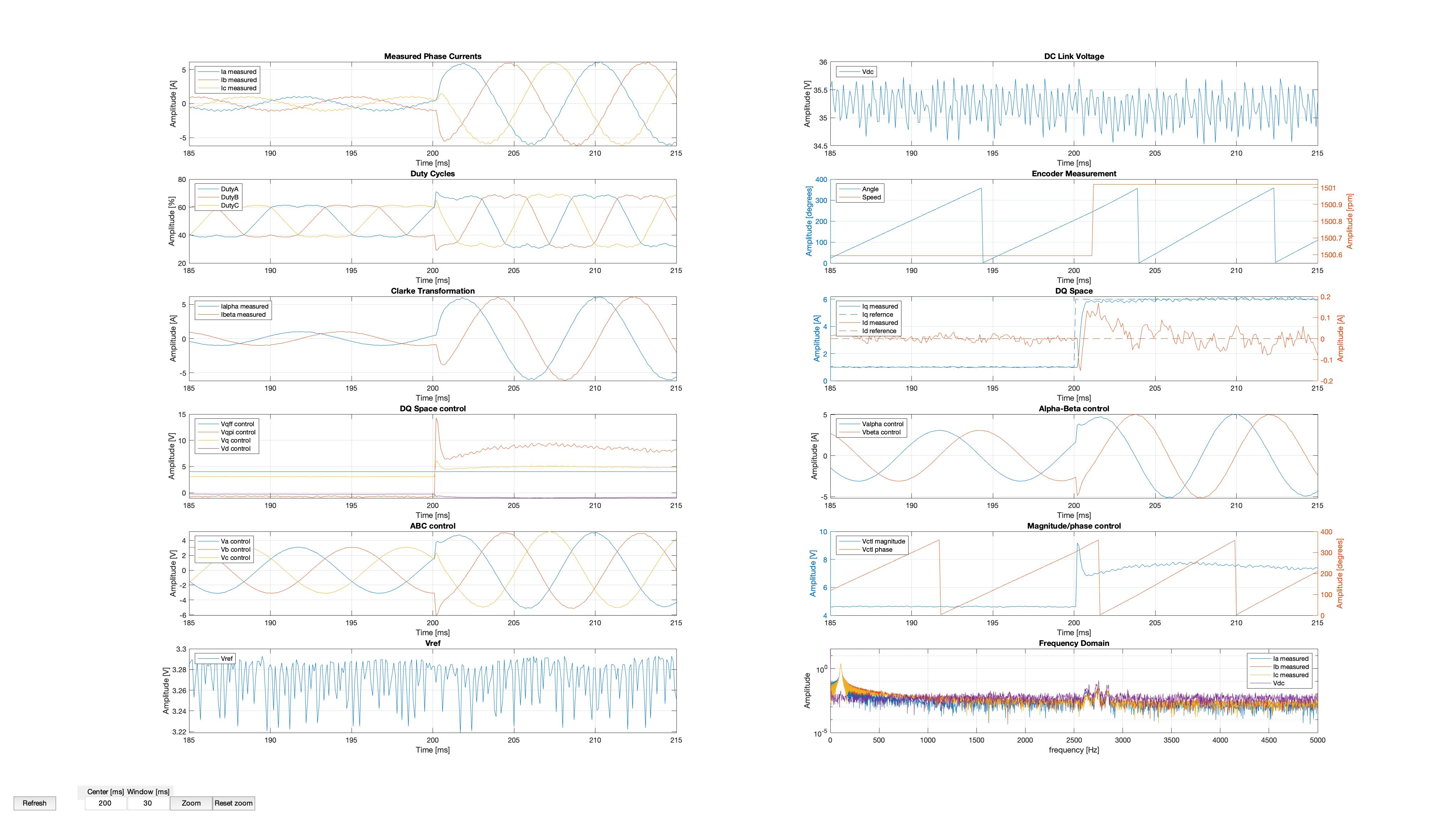
A 1A to 6A Quadrature step reference is shown in the figures above. The controller reacts immediately. Although the quadrature current follows very quickly the new reference, there is a slight increase in the peak phase current of the first half cycle, due to an increase of the direct current, as a result of the step change. This shoot is very quickly dumped and the inverter provides the three-phase current for the new torque request.
Generating mode step change
A similar behaviour is shown in an increase in the absolute value of the quadrature current when in energy recovery mode. No overshoot is seen on the quadrature or direct current values and the motor peaks up the new torque demand in less than a half wave period.
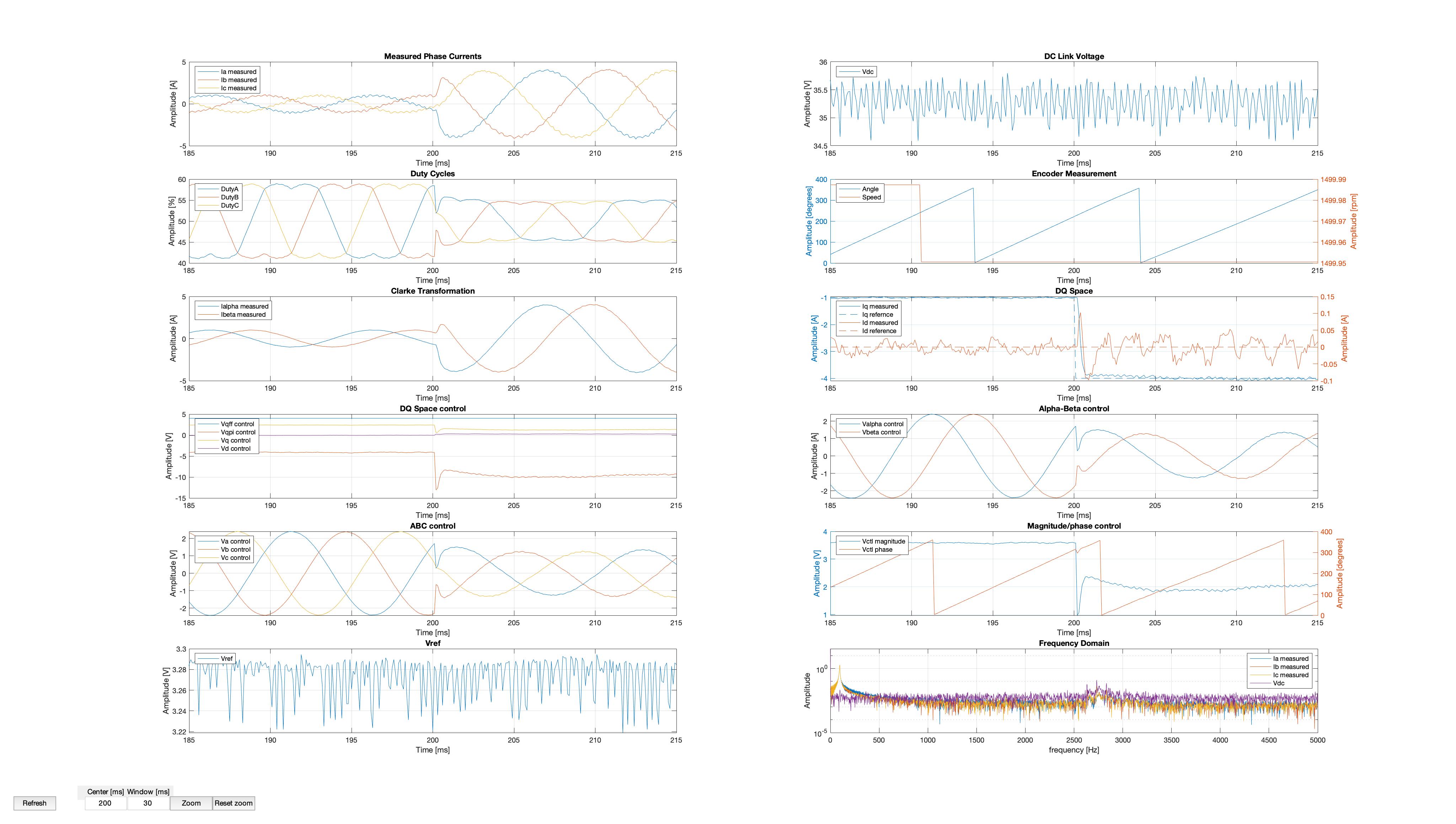
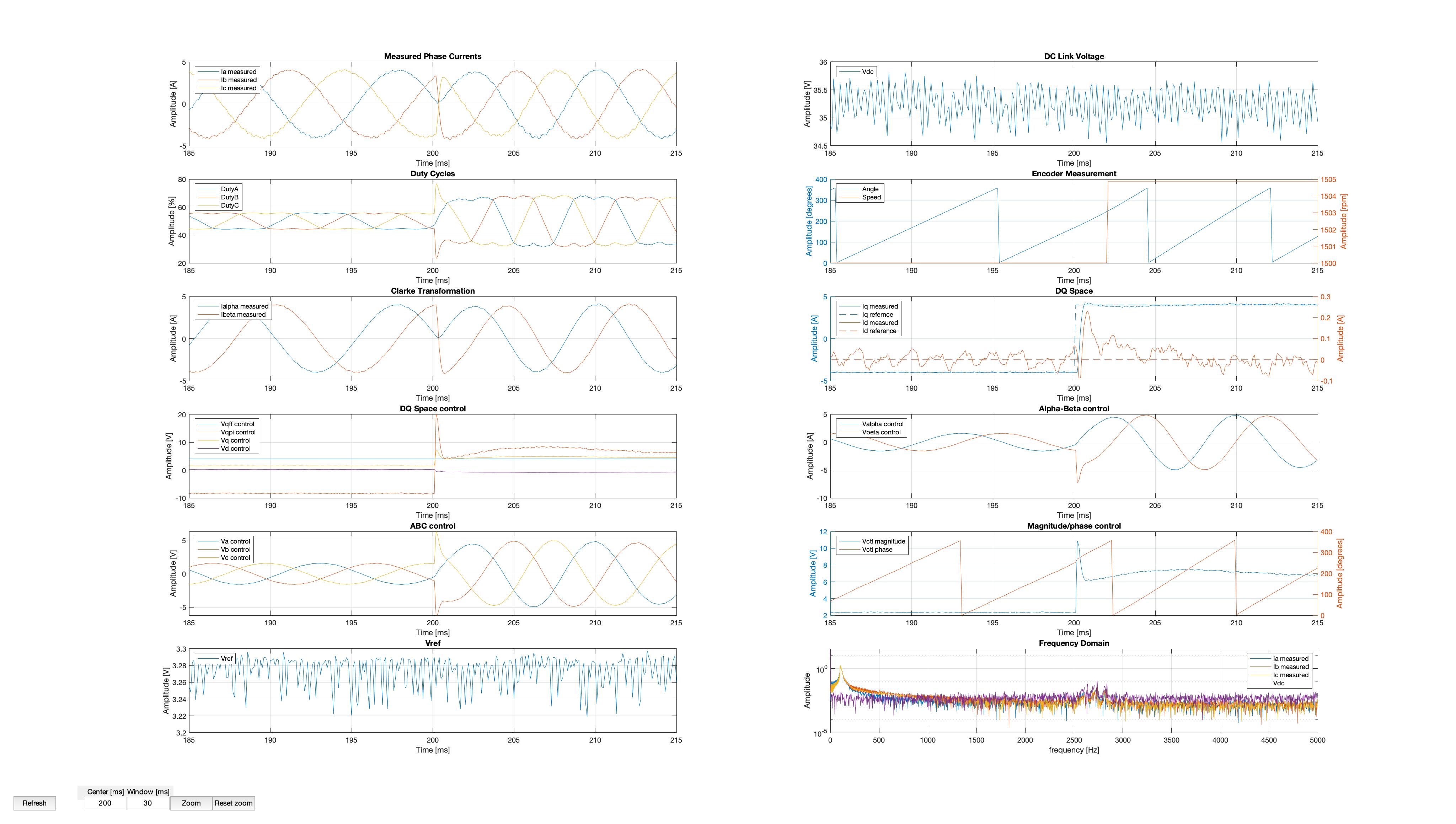
Motoring mode to generating mode step change
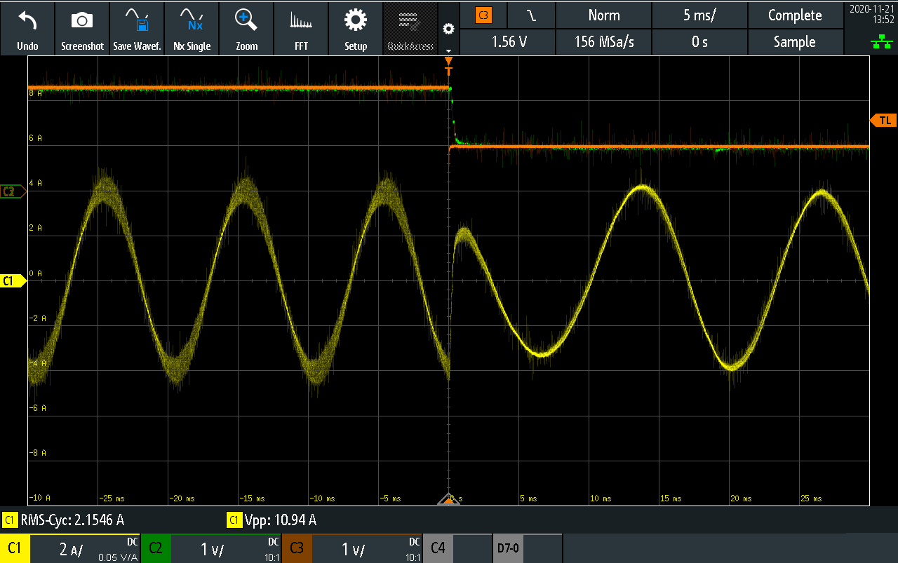
To evaluate the controller in even higher step disruptions, step changes between the two operating modes are conducted. On the figures above, a step quadrature current reference change from 4A to -4A is shown (direct current reference is 0A). The change in the phase of the current is quite significant. No overshoot is observed. Note the change in the angle rate, as the TI controller cannot keep the speed stead to its reference due to the major change on the load of the motor. There is a slight overshoot on the DC link during the switch of the roles of the two inverters.
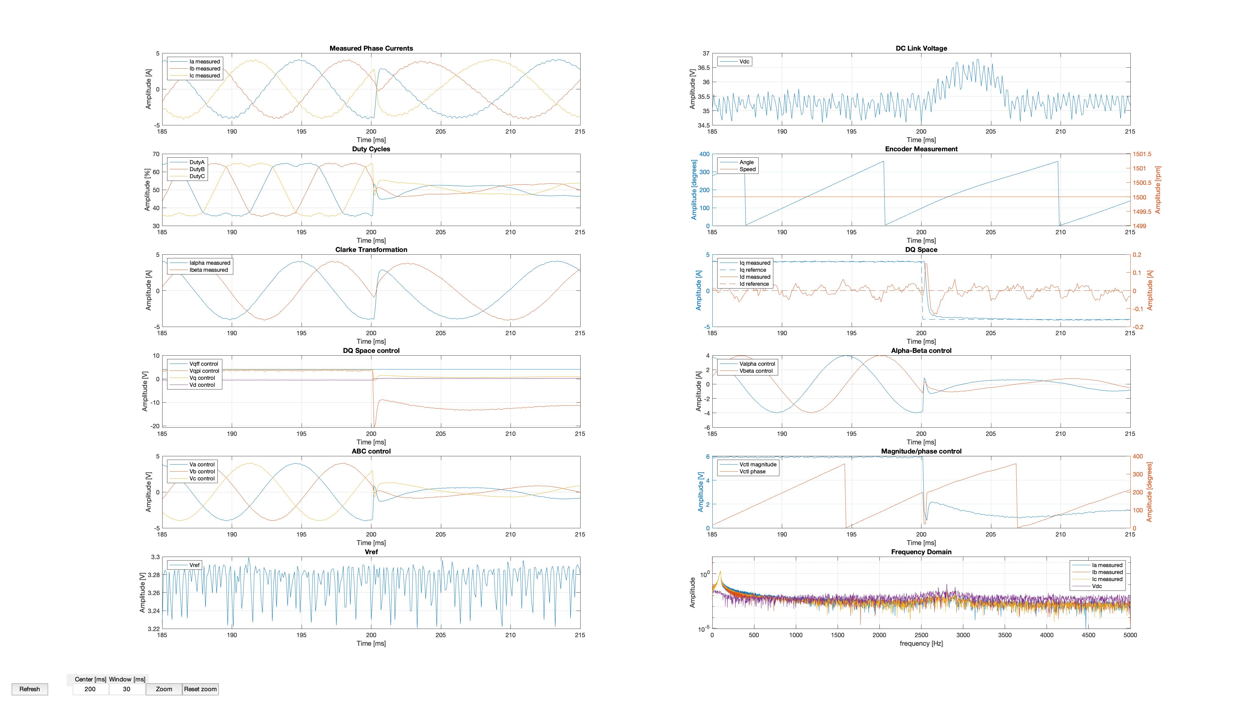
Generating mode to motoring step change
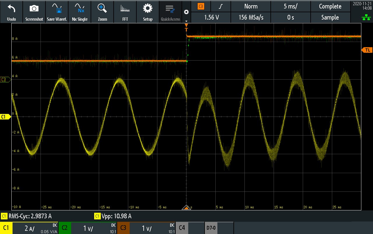
Similarly to the previous example, a step change from -4A to 4A on the quadrature current reference is conducted. Again, the developed controller can cope with the change, has a slight overshoot in peak phase current due to an increased direct current during the change, but goes to steady state in less than a fundamental period.