Based on my initial tests of Dot Matrix displays using either an FPGA or an STM32F4 microcontroller, I wanted to build a desk clock with the following features:
- Low drift using an external crystal
- Automatic setup using an NTP server via WiFi
- Support for daylight saving
- Temperature and Humidity measurement
- Periodic update using an NTP server
- Adjustable brightness
- Single 5V supply
- Minimum external components and wire connections
- Support for WiFi credentials reconfiguration
The Dot Matrix display I selected was a 64x32 RGB display which has a 5V supply input. The microcontroller I used was an STM32F767 which has a maximum clock frequency of 216MHz (important, since, as analyzed in previous articles, to achieve a high refresh rate, a high clock frequency is needed, especially as a microcontroller would be used instead of an FPGA, to keep the cost low).
The F767 is mounted on a Nucelo144 board. I selected the specific board because it had an on board 32.768kHz crystal as well as the necessary 3.3V regulator. A lower cost F4 Nucleo could also be used, but I also wanted to check some other features of the specific board (especially the hardware double precision FPU and the Ethernet PHY).
To get the time from an NTP server, I used a Wemos D1 mini board, which uses the well known ESP8266 chip. Again, the D1 mini board has a 3.3V regulator, a UART to USB converter, a USB port as well as the necessary pull up resistors for the ESP8266. I have used the ESP8266 before, when I built WiFi Power switch. The chip can be programmed through Arduino (using all the available Arduino libraries as well).
Concerning the temperature and humidity measurement (which was a late request), I selected the DHT21 (AM2301) single wire temperature and humidity sensor, which I have also used before when building the Raspberry Pi Meteo Station. It has a very good accuracy for the application, and, because of its popularity, many libraries are already available.
The connection diagram of the different components is shown below. The external 5V power supply (4A maximum current, <1A expected during operation), powers both the Dot Matrix Display as well as the Nucleo board, via the external 5V Vin pin. Through the Nucleo connectors, the 5V rail is also supplied to the Wemos D1 mini board, and is stepped down to 3.3V through the onboard regulator. 3.3V is also supplied to the DHT21 sensor via another Nucleo header connector.
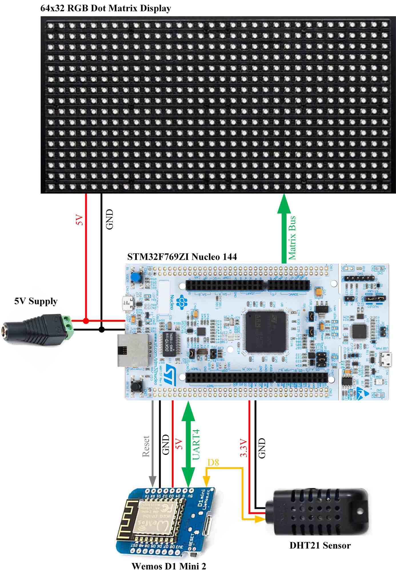
Concerning data transmission, the microcontroller and the ESP8266 will communicate via UART using a predefined protocol. In case of connection loss, the STM32 microcontroller will be able to reset the ESP8266 chip via the external reset pin, which is connected to an STM32 GPIO. The temperature sensor is also connected to the ESP8266 board, to decrease any processor load of the main STM32 microcontroller (which could result in display flickering if not taken into account). What is more, the matrix display data is sent through the GPIO peripheral of the microcontroller (13 pins in total) based on code analyzed previously.
The algorithm of the microcontroller also features
- 1 second interrupts (via the WakeUp RTC function) to update the display
- RTC alarm interrupt to get new NTP date and time
- Reset of the WiFi chip if no data is sent back
- Adjustable display brightness using the Nucleo User button
- UART interrupts for received data and error checking
The ESP8266 handles the WiFi connection (and update of credentials), temperature and humidity data from the DHT21 sensor, NTP time requests as well as daylight savings settings. To implement all of the above, the following libraries were used:
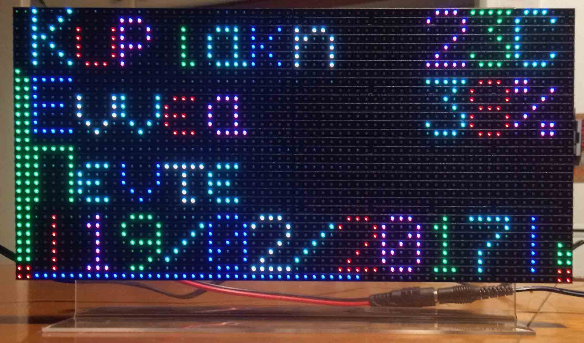
The data display format was based on a Bluetooth FPGA Dot matrix clock. In that case, each frame was constructed through a Matlab script and sent via Bluetooth to a Xilinx FPGA. As shown previously, the FPGA, because of its parallel data processing, can achieve higher color resolution (or higher FPS). However to operate, it would always need to be connected to a computer. The display features greek font support, hour and minute vertical bars (left and right side of the display respectively), a seconds bar on the bottom edge of the display as well as color animations.
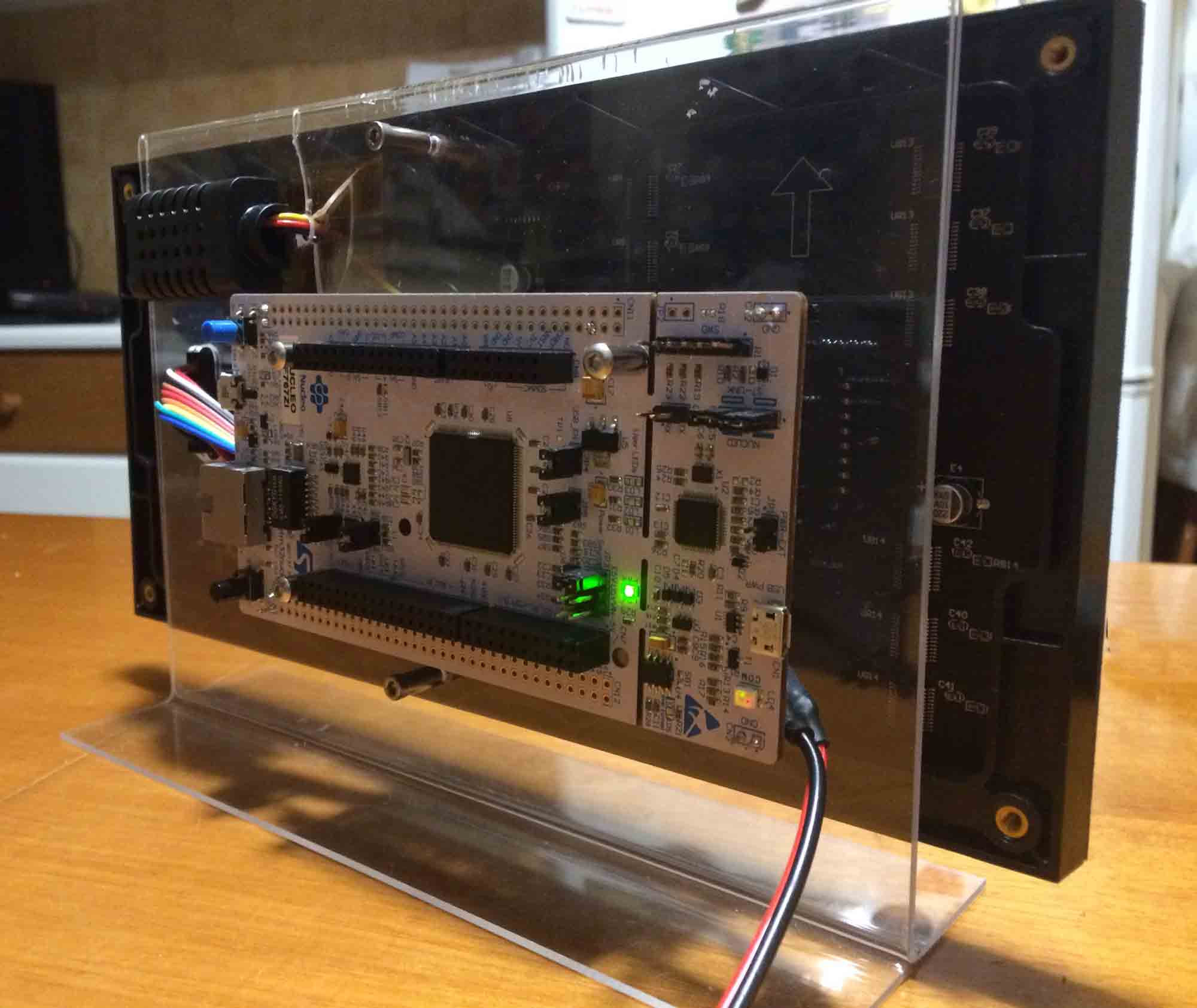
The mounting on the clock was also based on the above FPGA clock. The aim of the assembly was to eliminate any wires which would interconnect the four main components. All the wires are sandwiched between the Nucleo board on one side and the dot matrix display on the other side of the mount. The user button is accessible from the backside to change the display brightness, as well as the reset button. The micro-USB ports of the Nucleo board as well as the Wemos D1 mini board are also accessible for future firmware updates.