Comparison of 4 USB power supplies

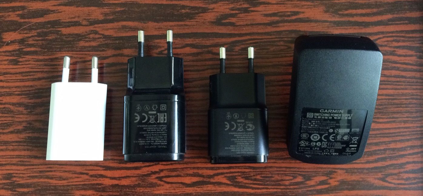
Having recently installed a Raspberry Pi 2 server running 24/7, which is powered through a 5V micro USB port (recommended power supply nominal current: 1.8A), I wanted to test different USB supplies in order to see which is the most efficient to use.

The models I tested were:

  1. Apple A1400 charger from an iPhone 4. Max. Current: 1A.
  2. LG MCS-04 charger from an LG phone. Max. Current: 1.8A.
  3. LG MCS-02 charger from an LG phone. Max. Current: 0.85A.
  4. Garmin PSAI05R-050Q charger from an Edge 510. Max. Current: 0.5A.

The tests were done powering a constant current load through a 1.5m USB cable, with a total resistance of 1Ω. The power losses of the cable were neglected as the aim was to measure the absolute efficiency of the wall chargers. The chargers were powered by 230V/50Hz and Zes Zimmer precision power analyzer was used to measure the efficiency and the power factor of each charger.

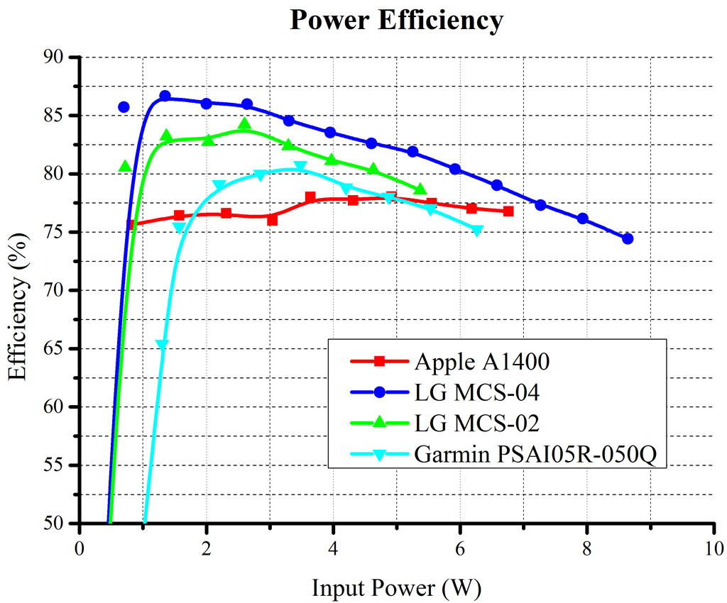
The results of the test are shown in the following figures.

First the results of the power efficiency are shown. The Garmin Charger has the lowest power rating and also the lowest efficiency. The LG MCS-04 which has the highest power rating, has also the highest efficiency. However, the Apple charger has a lower power efficiency than the LG MCS-02 charger, which has a lower rating. On the other hand, the Apple charger has the lowest standby power consumption (the power analyzer couldn't measure it) whereas it could measure some mW on all the other chargers.

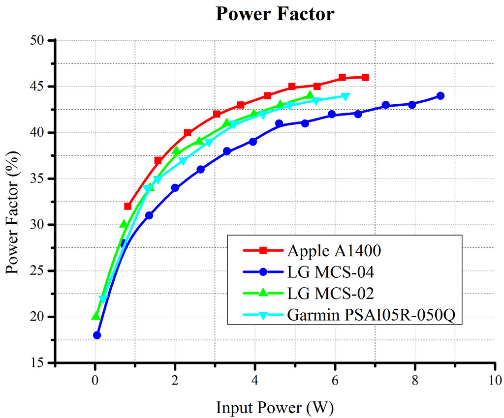
Next, the power factor measurements are shown in the following figure.

The power factor measurements are similar for all chargers and all very low. Yes, the chargers' input power is only some W, but there are millions plugged in at the same time. The power factor is expected to be this low due to the diode full bridge rectification of the ac voltage, followed by a capacitor, expected to have a high capacitance value, in order to help the output voltage stabilization (together with the DC/DC converter controller). Cheap counterfeits use a single-diode (half) rectification, so their power factor should be even lower.

All in all, although the power efficiency of the provided charger is not the main criterium when selecting a mobile phone, due to the large number of chargers, the suppliers were forced to improve the power efficiency of their chargers from 50% which was 15 years ago to over 75%. Also, certifications have been created (energy star, no load five star rating) to force the manufacturers to ship higher quality chargers.

The resistance of a 1.5m USB cable was 1Ω, which seems quite large. This means that for 1A, the voltage drop is 1V, and so, the phone would see only 4V during charging, so the power manager limits the demanded power, increasing the required time to charge. What is more, a complete measurement of the power efficiency of the complete system should also take into consideration the cable losses. That is why, in the modern era, 3m cables are extremely rare. To my knowledge only Nokia chargers for simple phones provide such a long cable. After sale long cables also exist for smart phones, designed to have similar resistance for an increased length at a cost of ~40$.

MATLAB code to create the characteristic of a PV Panel

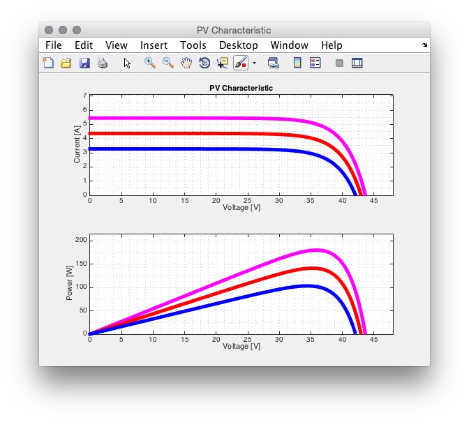
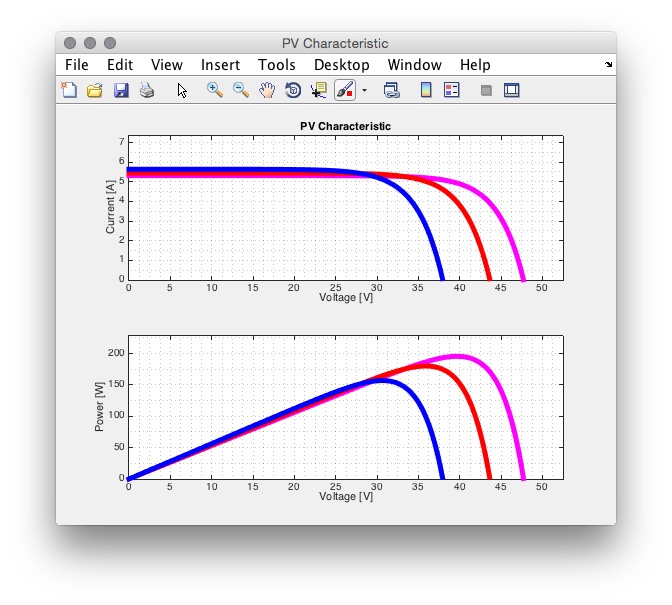
Photovoltaic (PV) panels are not constant voltage, current or power sources, but their output depend on the temperature or irradiance levels as well as on their connected load. This is why the power electronics converters connected on the output of the panel do not operate at a particular point, but are actively taking various measurements in order to determine which is the Maximum Power Point (MPP). The implemented algorithms can perform electrical measurements (i.e. voltage and current of the module) or environmental measurements (i.e. irradiance and temperature). The system designer needs to know the PV characteristic in order to specify the current and voltage limits of the power converter and how this will vary depending on the environmental conditions. PV suppliers always provide a PV characteristic for a nominal temperature of 25C and various irradiance levels (typically 1000W/m2, 800W/m2 and 600W/m2). They also provide temperature coefficient factors, which describe the effect of the temperature value to power output. However, since the photovoltaic phenomenon is accurately mathematically described, based on those equations, the PV characteristic can be derived for any irradiance or temperature value. The "Khouzam model" provides equations to produce such a characteristic based on parameters that are available by the PV manufacturers through their datasheet. So, a MATLAB program was created in order to implement the Khouzam model. The figure below shows the output characteristic of a MODULTEQ MTS180M-24V 180W panel for three different irradiance levels, namely 1000W/m2 (magenta), 800W/m2 (red) and 600W/m2 (blue). The effect of the irradiance level is clearly shown. The maximum PV output power decreases as the irradiance level decreases. What is more, the maximum (short circuit) current level deviation is more significant than the one of the maximum (open circuit) voltage.

A second figure shows the effect of the temperature on the PV panel output. The irradiance level is constant at 1000W/m2 but the PV panel temperature is 0C (magenta), 25C (red) and 60C (blue). This figure shows that when the temperature of the panel rises, the output power decreases. That is why cooling tubes that run on the back of the panels exist on certain installations. As the temperature rises the open circuit voltage decreases, whereas the short circuit current is not affected.

The full project of the Khouzam equations on MATLAB can be found on my Github page.

More TC74 programming on an STM32: Using sleep mode for low power

Previous posts showed how to use a TC74 temperature sensor with an STM32 microcontroller and how to handle communication errors . Since typically the temperature is not a value that changes rapidly, it is not essential to take multiple measurements with a high sampling rate, even if the I2C protocol is rather quick. For this reason, the TC74 sensor has a very low power standby mode when it not needed. The TC74 has an internal analog to digital converter which saves the value on an internal register. What is more this converter has a typical sampling rate of 8 samples per second. In standby mode this ADC is switched off. Concerning the power consumption, the information on the datasheet is a bit confusing. The datasheet provides a current consumption of 200uA in operating mode and 5uA in standby mode, which is a very significant difference. However, consumption in normal mode is measured for Vdd of 5.5V, whereas consumption in standby mode for Vdd of 3.3V. Based on my measurements of 2 TC74 operating in 3V, standby mode: 4uA, operating mode: 170uA. So indeed, the power saving is significant and should be used in low power applications. As it was analyzed, the TC74 has an 8-bit register which stores the temperature value. It has a second register (address 0x01), called the configuration register which has two bits. The first one (bit 7) enables the standby mode, whereas the second one (bit 6) shows when the sensor is ready to transmit the first data after entering operating operating. So the sequence to read the temperature using low power consumption is the following:

  1. Wake up
  2. Wait for the data to be ready (either using a delay or be polling the data ready bit of the config register
  3. Get temperature
  4. Sleep

After a wake up instruction, the TC74 needs about 300ms to transmit the first data. So in my implementation, a timer is used to wait for 500ms after a wake up instruction, get temperature and sleep the sensor and wait for 5s until the temperature is measured again. First of all, the TC74_Read_Temperature() function needs to be modified in order to read the 0x00 register (temperature) or the 0x01 register (configuration).

int TC74_Read_Register(uint8_t TC74address, uint8_t reg)

{

int8_t data1, data2;
if(I2C_start(I2C1, TC74address, I2C_Direction_Transmitter)>0) 
{ 
return -127; 
} 
if(I2C_write(I2C1, reg)>0) 
return -127; 
if(I2C_stop(I2C1)==1) 
return -127; 
if(I2C_start(I2C1, TC74address, I2C_Direction_Receiver)>0) 
{ 
return -127; 
} 
data1 = I2C_read_ack(I2C1); 
data2 = I2C_read_nack(I2C1); 
return data1; 
}


We need to have a status variable which will show whether the TC74 is in operating or standby mode.

typedef enum {TC74_SLEEPING, TC74_WAITING} TC74_statetypedef; 
TC74_statetypedef Temp_read_status=TC74_SLEEPING;


Two new functions are added, one that wakes up the sensor and another one that sends the instruction to enter standby mode.

int TC74_WakeUp(uint8_t TC74address) 
{ 
if(I2C_start(I2C1, TC74address, I2C_Direction_Transmitter)>0) 
{ 
return -127; 
} 
if(I2C_write(I2C1, 0x01)>0) 
return -127; 
if(I2C_write(I2C1, 0x00)>0) 
return -127; 
if(I2C_stop(I2C1)==1) 
return -127; 
return 0; 
} 
int TC74_Sleep(uint8_t TC74address) 
{ 
if(I2C_start(I2C1, TC74address, I2C_Direction_Transmitter)>0) 
{ 
return -127; 
} 
if(I2C_write(I2C1, 0x01)>0) 
return -127; 
if(I2C_write(I2C1, 0x80)>0) 
return -127; 
if(I2C_stop(I2C1)==1) 
return -127; return 0; 
}


After that we need to initialize a timer, TIM6 for the current example. The APB1 peripheral clock is 32MHz for the STM32L152.

void TIM6_Config(void) 
{ 
TIM_TimeBaseInitTypeDef timerInitStructure; 
NVIC_InitTypeDef NVIC_InitStructure; 
RCC_APB1PeriphClockCmd(RCC_APB1Periph_TIM6, ENABLE); 
timerInitStructure.TIM_Prescaler=1000; 
timerInitStructure.TIM_CounterMode=TIM_CounterMode_Up; 
timerInitStructure.TIM_Period=32000; 
timerInitStructure.TIM_ClockDivision=TIM_CKD_DIV1; 
TIM_TimeBaseInit(TIM6, &timerInitStructure); 
TIM_Cmd(TIM6, ENABLE); 
NVIC_InitStructure.NVIC_IRQChannel = TIM6_IRQn; 
NVIC_InitStructure.NVIC_IRQChannelCmd = ENABLE; 
NVIC_InitStructure.NVIC_IRQChannelPreemptionPriority = 8; 
NVIC_InitStructure.NVIC_IRQChannelSubPriority = 0; 
NVIC_Init(&NVIC_InitStructure); 
TIM_ITConfig(TIM6, TIM_IT_Update, ENABLE); 
}


The interrupt handler routine of TIM6 is:

void TIM6_IRQHandler(void) 
{ 
if (TIM_GetFlagStatus(TIM6, TIM_IT_Update)!=RESET) 
{ 
TIM_Cmd(TIM6, DISABLE);
if (Temp_read_status==TC74_SLEEPING) 
{ 
TC74_WakeUp(TC74_ADDRESS); 
TIM6->PSC = 5000; 
Temp_read_status=TC74_WAITING; 
} 
else 
{ 
Temperature=TC74_Read_Register(TC74_ADDRESS,0x00); 
TC74_Sleep(TC74_ADDRESS); 
TIM6->PSC = 500; 
Temp_read_status=TC74_SLEEPING; 
} 
TIM6->CNT=0; 
TIM_Cmd(TIM6, ENABLE); 
TIM_ClearITPendingBit(TIM6, TIM_IT_Update); 
} 
}

The full project to read the temperature from the TC74 sensor with error handling and standby mode can be found on my Github page.

More TC74 on STM32: Avoiding I2C bus failure when TC74 doesn't respond

On a previous post, the code to implement the I2C protocol for an STM32 microcontroller connected to an TC74 temperature sensor was implemented. However, what happens if no TC74 is connected or due to a failure does not respond. Since the TC74 sensor will be used on the UPSat mission, the microcontroller needs to be able to acknowledge that the sensor does not respond and continue with executing the main program.

One peripheral that can be used in case the TC74 doesn't respond is the watchdog counter. If no error handling is implemented on the I2C communication, the program enters into a deadlock. The watchdog's purpose is to reset the microcontroller if it doesn't reset the watchdog counter after a short period of time, acting as an auto reset. The STM32 micro controllers include independent and window watchdogs. However, on the next time that the temperature sensor will be called again, the microcontroller will freeze again. Of course, a "reset reason" detection code could be implemented and disable TC74 communication after a reset caused to an I2C error, but the damage to the procedure execution could already be done because of the reset.

A more correct way is to implement error handling on the I2C communication and continue code execution when an error is detected, discarding the measurement. The microcontroller after sending a message through the I2C bus waits for the peripheral to respond. If the peripheral does not respond, the code execution freezes at this point. The simplest solution is to implement a timeout function, meaning that if the peripheral does not respond after a certain amount of time, the code execution will continue. The I2C peripheral on the STM32 microcontroller does not implement a timeout support inherently. However, the System Management Bus (SMBus) mode can be used which implements timeout detection. So, on the initialization function of the I2C peripheral, the I2C_mode needs to be set to I2C_Mode_SMBusHost. Then, using the I2C Timeout flag or the I2C Timeout interrupt, the error can be handled.

Furthermore, another error that can appear is an acknowledge failure. This exists when the microcontroller sends a message to the device, awaits for an acknowledge bit on the next clock but it doesn't respond. Again, the Acknowledge Failure (AF) flag can be polled to detect the error.

So based on the above, the communication protocol functions are rewritten to return 0 is the communication is good and >0 if there is an error. The main function finally returns the temperature, or -127 in case of an error:

int TC74_Read_Temperature(uint8_t TC74address)
{
int8_t data1, data2;
if(I2C_start(I2C1, TC74address, I2C_Direction_Transmitter)>0) {
I2CBus_Reset();
return -127;
}
if(I2C_write(I2C1, 0x00)>0) return -127;
if(I2C_stop(I2C1)==1) return -127;

if(I2C_start(I2C1, TC74address, I2C_Direction_Receiver)>0) {
I2CBus_Reset();
return -127;
}
data1 = I2C_read_ack(I2C1);
data2 = I2C_read_nack(I2C1);

return data1;
}

So the modification that is implemented is inside the while statement to avoid the infinite loop. If an error flag is set, the code execution is stopped, returning the error code.

int I2C_start(I2C_TypeDef* I2Cx, uint8_t address, uint8_t direction)
{
int i2c_timeout=I2CTIMEOUT;
while(I2C_GetFlagStatus(I2Cx, I2C_FLAG_BUSY));

I2C_GenerateSTART(I2Cx, ENABLE);

while(!I2C_CheckEvent(I2Cx, I2C_EVENT_MASTER_MODE_SELECT)){
if(I2C_GetFlagStatus(I2Cx, I2C_FLAG_TIMEOUT)!=RESET) {
I2C_ClearFlag(I2Cx, I2C_FLAG_TIMEOUT);
return 1;
}
if(I2C_GetFlagStatus(I2Cx, I2C_FLAG_AF)!=RESET) {
I2C_ClearFlag(I2Cx, I2C_FLAG_AF);
return 2;
}
}
I2C_Send7bitAddress(I2Cx, address, direction);

if (direction== I2C_Direction_Transmitter) {
while(!I2C_CheckEvent(I2Cx, I2C_EVENT_MASTER_TRANSMITTER_MODE_SELECTED)){
if (I2C_GetFlagStatus(I2Cx, I2C_FLAG_TIMEOUT)!=RESET) {
I2C_ClearFlag(I2Cx, I2C_FLAG_TIMEOUT);
return 1;
}
if(I2C_GetFlagStatus(I2Cx, I2C_FLAG_AF)!=RESET) {
I2C_ClearFlag(I2Cx, I2C_FLAG_AF);
return 2;
}
}
}

else if(direction == I2C_Direction_Receiver) {
while(!I2C_CheckEvent(I2Cx, I2C_EVENT_MASTER_RECEIVER_MODE_SELECTED)){
if (I2C_GetFlagStatus(I2Cx, I2C_FLAG_TIMEOUT)!=RESET) {
I2C_ClearFlag(I2Cx, I2C_FLAG_TIMEOUT);
return 3;
}
if(I2C_GetFlagStatus(I2Cx, I2C_FLAG_AF)!=RESET) {
I2C_ClearFlag(I2Cx, I2C_FLAG_AF);
return 4;
}
}
}
return 0;
}
int I2C_write(I2C_TypeDef* I2Cx, uint8_t data)
{
I2C_SendData(I2Cx, data);

while(!I2C_CheckEvent(I2Cx, I2C_EVENT_MASTER_BYTE_TRANSMITTED)){
if (I2C_GetFlagStatus(I2Cx, I2C_FLAG_TIMEOUT)!=RESET) {
I2C_ClearFlag(I2Cx, I2C_FLAG_TIMEOUT);
return 1;
}
if(I2C_GetFlagStatus(I2Cx, I2C_FLAG_AF)!=RESET) {
I2C_ClearFlag(I2Cx, I2C_FLAG_AF);
return 2;
}
}
return 0;
}
int I2C_stop(I2C_TypeDef* I2Cx)
{
I2C_GenerateSTOP(I2Cx, ENABLE);
return 0;
}
int8_t I2C_read_ack(I2C_TypeDef* I2Cx)
{
int8_t data;

I2C_AcknowledgeConfig(I2Cx, ENABLE);
while(!I2C_CheckEvent(I2Cx, I2C_EVENT_MASTER_BYTE_RECEIVED)){
if (I2C_GetFlagStatus(I2Cx, I2C_FLAG_TIMEOUT)!=RESET) {
I2C_ClearFlag(I2Cx, I2C_FLAG_TIMEOUT);
return -127;
}
if(I2C_GetFlagStatus(I2Cx, I2C_FLAG_AF)!=RESET) {
I2C_ClearFlag(I2Cx, I2C_FLAG_AF);
return -127;
}
}
data=I2C_ReceiveData(I2Cx);

return data;
}
int8_t I2C_read_nack(I2C_TypeDef* I2Cx)
{
uint8_t data;

I2C_AcknowledgeConfig(I2Cx, DISABLE);
I2C_GenerateSTOP(I2Cx, ENABLE);

while(!I2C_CheckEvent(I2Cx, I2C_EVENT_MASTER_BYTE_RECEIVED)){
if (I2C_GetFlagStatus(I2Cx, I2C_FLAG_TIMEOUT)!=RESET) {
I2C_ClearFlag(I2Cx, I2C_FLAG_TIMEOUT);
return -127;
}
}
data=I2C_ReceiveData(I2Cx);

return data;
}

The full project to read the temperature from the TC74 sensor with error handling can be found on my Github page.

Temperature monitoring with TC74 on an STM32 microcontroller

The TC74 is a small thermal sensor with a wide temperature range (-40C to +125C) and a digital output (I2C). It comes in a TO-220 package or a small scale SOT-23 package and is powered by 3.3V or 5V. Based on the above it was for our UPSat, as two temperature values (board temperature and battery temperature) need to be measured every minute. The TC74 can withstand the temperature conditions found inside the Cubesat and can provide relatively accurate measurements, with low power consumption.

The majority of thermal sensors have an analog output, the value of which is given as a function of the measured temperature. So, the measurement is susceptible to noise, as the Analog to Digital converter used is found in the micro-controller and each sensor needs an extra pin. On the other hand the TC74 has an embedded ADC and transmits the data digitally, via the I2C Serial Port Interface. The I2C protocol is used for the communication of different ICs on a board with the micro-controller, for example EEPROMs, ADCs or GPIO expanders. It needs two lines, the SDA (data) and the SCL (clock). The lines are pulled high and the ICs pull the lines low. It uses a master/slave approach, where the micro controller is usually the master and therefore is responsible for the SCL line.

Having studied other communication protocols, the I2C is rather peculiar and especially the implementation of the protocol on the TC74. The default address length is 7bits. It can be 10 bits as well. To establish communication, the sender first issues a start condition. It then continues by sending the address of the peripheral that it needs to communicate with and finally a bit showing whether it wants to read data from the device or write data to the device. It then awaits for the an acknowledge (ACK) bit from the device on the next clock sequence and continues the communication accordingly.

The way this protocol is implemented on the TC74 is as follows. The TC74 has two registers, the temperature register, which has the temperature value and the control register (which is used to limit power consumption). So, to read the temperature, the micro-controller first issues a start bit, followed by the 7bit address of the TC74. The TC74 then sends an ACK. The micro-controller then sends the address of the register that it wants to read. In the case of the temperature register, the value is 0x00. The TC74 sends an ACK again. After that, the micro-controller sends a start condition again, the address of the TC74 again followed by an ACK and waits for the data followed by a NACK (not-acknowledge). It finally issues a stop condition.

The code shown bellow implements the communication of a single TC74 with an STM32L152 micro-controller. The pins used are PB6 and PB7 and the I2C1 peripheral was used. The STM32 internal pull-up resistors were used.

The TC74 have 8 different product codes depending on the factory written addresses of the chip. So on a single I2C bus, 8 different TC74 can be used. In this example the TC74A5 is used:

#define TC74_ADDRESS 0x9A

Next, the init function needs to be implemented:

void TC74_Config(void)
{
GPIO_InitTypeDef GPIO_InitStructure;
I2C_InitTypeDef I2C_InitStructure;
RCC_AHBPeriphClockCmd(RCC_AHBPeriph_GPIOB, ENABLE);
RCC_APB1PeriphClockCmd(RCC_APB1Periph_I2C1, ENABLE);

GPIO_PinAFConfig(GPIOB, GPIO_PinSource6, GPIO_AF_I2C1);
GPIO_PinAFConfig(GPIOB, GPIO_PinSource7, GPIO_AF_I2C1);
GPIO_StructInit(&GPIO_InitStructure);
GPIO_InitStructure.GPIO_Mode = GPIO_Mode_AF;
GPIO_InitStructure.GPIO_Speed = GPIO_Speed_40MHz;
GPIO_InitStructure.GPIO_OType = GPIO_OType_PP;
GPIO_InitStructure.GPIO_PuPd = GPIO_PuPd_UP;
GPIO_InitStructure.GPIO_Pin = GPIO_Pin_6 | GPIO_Pin_7;
GPIO_Init(GPIOB, &GPIO_InitStructure);
I2C_InitStructure.I2C_Ack = I2C_Ack_Enable;
I2C_InitStructure.I2C_AcknowledgedAddress = I2C_AcknowledgedAddress_7bit;
I2C_InitStructure.I2C_ClockSpeed = 10000;
I2C_InitStructure.I2C_Mode = I2C_Mode_SMBusHost;
I2C_InitStructure.I2C_OwnAddress1 = 0x00;
I2C_Init(I2C1, &I2C_InitStructure);
I2C_Cmd(I2C1, ENABLE);
}

This function initializes the I2C1 peripheral, the ports PB6, PB7 and activates the pull-up resistors.

Next is where the fun stuff begins. The timing sequence is implemented with different functions. The main function to return an integer value of the temperature is:

int TC74_Read_Temperature(uint8_t TC74address)
{
int8_t data1, data2;
I2C_start(I2C1, TC74address, I2C_Direction_Transmitter);
I2C_write(I2C1,0x00);
I2C_stop(I2C1);
I2C_start(I2C1, TC74address, I2C_Direction_Receiver);
data1 = I2C_read_ack(I2C1);
data2 = I2C_read_nack(I2C1);
return data1;
}

Finally each of these functions are described as well:

void I2C_start(I2C_TypeDef* I2Cx, uint8_t address, uint8_t direction)
{
while(I2C_GetFlagStatus(I2Cx, I2C_FLAG_BUSY));
I2C_GenerateSTART(I2Cx, ENABLE);
while(!I2C_CheckEvent(I2Cx, I2C_EVENT_MASTER_MODE_SELECT)) ;
I2C_Send7bitAddress(I2Cx, address, direction);
if (direction== I2C_Direction_Transmitter) {
while(!I2C_CheckEvent(I2Cx, I2C_EVENT_MASTER_TRANSMITTER_MODE_SELECTED));
}
else if(direction == I2C_Direction_Receiver) {
while(!I2C_CheckEvent(I2Cx, I2C_EVENT_MASTER_RECEIVER_MODE_SELECTED));
}
}
void I2C_write(I2C_TypeDef* I2Cx, uint8_t data)
{
I2C_SendData(I2Cx, data);
while(!I2C_CheckEvent(I2Cx, I2C_EVENT_MASTER_BYTE_TRANSMITTED));
}
void I2C_stop(I2C_TypeDef* I2Cx)
{
I2C_GenerateSTOP(I2Cx, ENABLE);
}
int8_t I2C_read_ack(I2C_TypeDef* I2Cx)
{
int8_t data;
I2C_AcknowledgeConfig(I2Cx, ENABLE);
while(!I2C_CheckEvent(I2Cx, I2C_EVENT_MASTER_BYTE_RECEIVED));
data=I2C_ReceiveData(I2Cx);
return data;
}
int8_t I2C_read_nack(I2C_TypeDef* I2Cx)
{
uint8_t data;
I2C_AcknowledgeConfig(I2Cx, DISABLE);
I2C_GenerateSTOP(I2Cx, ENABLE);
while(!I2C_CheckEvent(I2Cx, I2C_EVENT_MASTER_BYTE_RECEIVED));
data=I2C_ReceiveData(I2Cx);
return data;
}

The full project to read the temperature from the TC74 sensor can be found on my Github page.